My '76 restoration (long post)

VetteMod - Corvette Restoration, Modding & Performance Forum

Help Support VetteMod Forum:

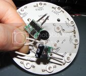
Yesterday I had time to solder the led driver I received, those are really tiny and I think I will put two of there between each taillight, reducing the central control unit size and complexity.
hipowerled0.jpg

One is a 650 mA to drive the two 5 led rows of red led, the other one is a 325 mA to drive the central single 5 led row. Both seems to fit each configuration mA bill.

UnfortunatelyI have to report setback on this sub-project.
First, I ordered the wrong drivers, those are using the quiet antiquated MC34063 chip, while I need drivers built on the PT4115 whose offer dedicated PWM dimming pin.

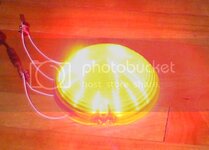
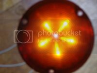
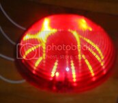
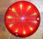
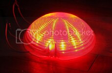
Secondly, I fired my led with my non dimmable drivers, and boy, what a light show. I'm nearing the too-bright-to-face level which is a good starting point :devil:
hipowerled1.jpg

hipowerled4.jpg

hipowerled3.jpg


hipowerled5.jpg


hipowerled2.jpg

I know it's ridiculous trying to take picture of direct light source, and those was so powerful my camera wasn't too happy trying to adapt to the intensity.
I definitely will need some dimming, at least 30% down. The bad thing it that leds are spreading too much, causing nasty flares when view sideways. So just ordered a set of 5° focusing lens along with the correct led drivers.
 
Last edited:
Hi everyone, I had a very busy week but finally I could log some hours on the project today.

I installed the headlight. God those things are PITA to install and adjust.

Driver:
headlight7.jpg

headlight5.jpg


Passenger:

headlight4.jpg

headlight6.jpg

Still not pleased by the alignment, but this is a two persons job, and my helping hand du jour could stay any long.
Not a problem, this was not my actual goal, I wanted to try a headlight mod :

headlight2.jpg

headlight1.jpg

headlight3.jpg


I implemented the design proposed by BBShark(VM).
It don't open enough, and the open state is not really stable anymore, you can close the door with little pressure on the headlight flap. Still a good start, to be continued.


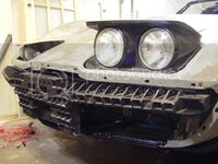
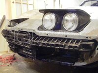
Also as you can see I'm done with the bumper assembly. Here again a PITA, lots of parts to interconnect, bolts everywhere.

frontbumper1.jpg

While I was a it I reinstalled the horns.

frontbumper2.jpg


frontbumper3.jpg

I'm still looking to get a set of spoiler, but in the meanwhile the stock spoiler is better on the car that on a shelve. Anyhow, it's more about checking if I have all the brackets and the bolts than doing a final assembly.

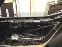
Thank to Roco71(CF) I could finish my passenger door.
doorcover.jpg


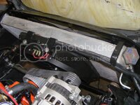
And as I said before, the radiator is back in place, with coolant.
radiator2.jpg

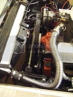
The more I see my radiator, the more I think it's ridiculously tiny. Next time I hit the scrapyard I'll look for some twin fan setup.

radiator1.jpg
 
I implemented the design proposed by BBShark(VM).
It don't open enough, and the open state is not really stable anymore, you can close the door with little pressure on the headlight flap. Still a good start, to be continued.

headlight1.jpg

Something is not correct there. The headlight door should be basically level and yours looks like the front edge is lower than the back. The link has to go over center. If it goes over center you won't be able to push it down, not without breaking something.
 
I implemented the design proposed by BBShark(VM).
It don't open enough, and the open state is not really stable anymore, you can close the door with little pressure on the headlight flap. Still a good start, to be continued.

headlight1.jpg

Something is not correct there. The headlight door should be basically level and yours looks like the front edge is lower than the back. The link has to go over center. If it goes over center you won't be able to push it down, not without breaking something.

I will get a second look tomorrow and take pictures.
 
[

Something is not correct there. The headlight door should be basically level and yours looks like the front edge is lower than the back. The link has to go over center. If it goes over center you won't be able to push it down, not without breaking something.

Mike, I've checked the headlight tonight, and you was correct, there was something wrong.

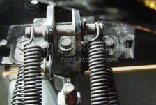
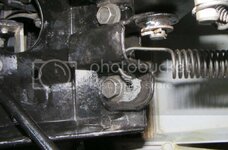
There is one variable of the headlight tuning equation I overlooked : the position of the linkage axis, hold by those bolts :

headlightlink0.jpg


If I let the axis go all the way to the back :

headlightlink2.jpg


Then headlight reach the position we were expecting, flat horizontal, in a locked resting state :

headlightlink3.jpg

Even it I start to wondering if I can afford those sexy (and pricey) 90mm headlight, it looked as good as I expected.


BUT then the closed state don't work anymore, the mechanism don't have strenght anymore to more the headlight past that point :

headlightlink1.jpg

It hasn't reached the adjustement screw head yet and is basicaly floating.


When I installed the headlight, I was basically in the opposite situation: axis all the way to the other side, nice closing but incomplete opening.


So I tried to find a compromise position but after a good dozen of attempts I start to wonder if the two ranges even overlaps.
I know you're using 3D physic simulator on a regular basis, was the headlights motion simulated?
Sometimes I miss my huge box of Legos, I used to create some pretty wicked mechanisms with them when I was kid.
 
As an Amazon Associate we earn from qualifying purchases. Product prices and availability are accurate as of the date/time indicated and are subject to change.
Something is not correct there. The headlight door should be basically level and yours looks like the front edge is lower than the back. The link has to go over center. If it goes over center you won't be able to push it down, not without breaking something.

Mike, I've checked the headlight tonight, and you was correct, there was something wrong.

If I let the axis go all the way to the back :
Then headlight reach the position we were expecting, flat horizontal, in a locked resting state :

BUT then the closed state don't work anymore, the mechanism don't have strenght anymore to more the headlight past that point :

It hasn't reached the adjustement screw head yet and is basicaly floating.

When I installed the headlight, I was basically in the opposite situation: axis all the way to the other side, nice closing but incomplete opening.

Jim, Something is still not right. I don't see the link in the pictures so I can't say.

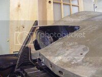
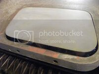
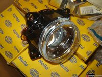
The Hellas also are much deeper that the sealed beams. So, you have to cut up the door pretty good
 
Something is not correct there. The headlight door should be basically level and yours looks like the front edge is lower than the back. The link has to go over center. If it goes over center you won't be able to push it down, not without breaking something.

Mike, I've checked the headlight tonight, and you was correct, there was something wrong.

If I let the axis go all the way to the back :
Then headlight reach the position we were expecting, flat horizontal, in a locked resting state :

BUT then the closed state don't work anymore, the mechanism don't have strenght anymore to more the headlight past that point :

It hasn't reached the adjustement screw head yet and is basicaly floating.

When I installed the headlight, I was basically in the opposite situation: axis all the way to the other side, nice closing but incomplete opening.

Jim, Something is still not right. I don't see the link in the pictures so I can't say.

The Hellas also are much deeper that the sealed beams. So, you have to cut up the door pretty good
Pretty tough to get picture now the headlights are in, but I'll try, even for the sake of validating your design, because I didn't realise the depth difference and no I won't cut my doors for that.
 
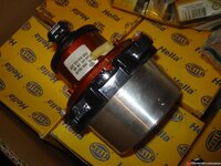
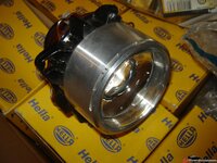
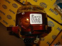
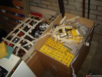
I have a couple (2 large boxes full) of those 90mm modules hi beams, SAW & EU lo beams, some with spiffy alu covers :)

24a33c9bddc9e5.jpg

24a33c9bf03539.jpg

24a33c9c025808.jpg

24a33c9c15daae.jpg

24a33c9c258c70.jpg
 
I'd love to update the lights on my C3 with projector lights - but I'm afraid with my lack of knowledge on the subject I'd have boxes full of lights that don't work or aren't legal...
 
I have a couple (2 large boxes full) of those 90mm modules hi beams, SAW & EU lo beams, some with spiffy alu covers :)

If only running a high beam and a low beam the overall cost it kina ok, but if you want to get a hi-low beam to have two low beam, prices get unsane.
Anyhow, they look really deep and as said, I won't cut my light doors.
 
I have a couple (2 large boxes full) of those 90mm modules hi beams, SAW & EU lo beams, some with spiffy alu covers :)

So, TT - those fall off a Truck? Hell of a deal you've got there - thinking of becoming a distributor? If interested in selling any, do you have a price for a set of 2+2?

Cheers - Jim
 
I have a couple (2 large boxes full) of those 90mm modules hi beams, SAW & EU lo beams, some with spiffy alu covers :)

So, TT - those fall off a Truck? Hell of a deal you've got there - thinking of becoming a distributor? If interested in selling any, do you have a price for a set of 2+2?

Cheers - Jim
I'm afraid shipping price from Europe would offset any deal he could make you.
 
What's the running jokes with name here, did I screw up someone name???

?:confused:
First Mike call me Jim, then Kastern call Mike Steeve, then Mike calls Kastern Fred....:confused::confused:
:eek: brings back olde tyme memories, 1/2 a century ago in college there was a German fellow in the dorm, and he had the typical heavy accent, just like Karsten today....his 'handle' was Sauerkraut.......
Hal was a good guy, he dished it out good as he got....

:smash::thumbs:
 
I have a couple (2 large boxes full) of those 90mm modules hi beams, SAW & EU lo beams, some with spiffy alu covers :)

So, TT - those fall off a Truck? Hell of a deal you've got there - thinking of becoming a distributor? If interested in selling any, do you have a price for a set of 2+2?

Cheers - Jim
I'm afraid shipping price from Europe would offset any deal he could make you.

EH, doubtful it would EVER equal shipping a box of bolts.....

I let TT tell you about that one.......:eek::twitch:
 
Hey Larry, found the problem with the shortened headlight lilnkage.

headlightlink5_zpsfaa04bff.jpg

headlightlink4_zps1a5a186d.jpg

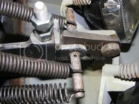
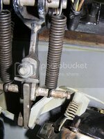
First there was the outer spring that was hitting the headlight support, and when I removed it, that was the bar itself that hit the support.
The stop tab almost reach its destination.

At least that validates the motion range, now I have clear stable state on both end of the motion, but even with modified spring I don't think the headlight support is going to be happy to be hit every time.
 
It is close on mine but the springs clear the doors. The link should just barely go past center when locked in the up position. Clearancing the doors would be pretty easy also.
 
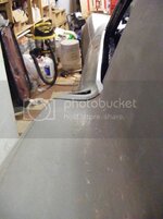
To the list of things done, I can add my door upper curve fitting.
After ungluing the fiberglass, banging the suporting metal frame and gluing it again, I now have pretty decently matching body curves

doorgapgooddriver2_zps75d786e2.jpg

doorgapgooddriver1_zpsf3842003.jpg

doorgapgoodpassenger1_zps774ae9fd.jpg

doorgapgoodpassenger2_zps478be59b.jpg


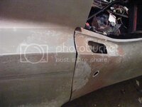
Then I started the body seams.
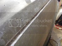
First I chiseled out the original glue down to the underlying bonding strip

fenderseam2_zpsb154451e.jpg


fenderseam3_zpse9b0ab23.jpg


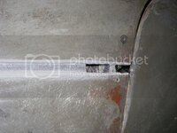
Here you can see I cut the bonding strip at the back of the front clip. At the time I found it was easier for adjusting the front clip with the doors.

fenderseam1_zpse46defef.jpg


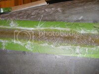
Then I ground a slope along both side of the fiberglass.
With a mix of epoxy and fiberglass powder I then filled the gap formed by the glue. So I got a continuous V shaped groove.
Sorry no pic of that, will take one when I do the next seams.

Then glassing.
If I'd say I got it right the first time I'd be lying big time.
Took me 4 attempts go get it right. Each time I had to remove everything and start from scratch.
My biggest mistake, and it's a newbie one, was not to break the fiber before laying it.
Basically I was trying to make piece of fiberglass rigid as cardboard to stick to in a concave shape. Did not fly.
It was ok doing this way when the surface are flat and/or can be kept under compression while curing, like all the repairs had to do so far.
I had to get back to fellow restorers thread to understand that.
So with every patch of fiberglass mat gently pulled in every direction until it get soft as cloth, I could finally math by fiberglass to follow the shape.

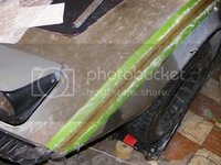
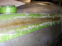
fenderseam6_zpsf115e122.jpg

fenderseam5_zps9449b8c7.jpg


fenderseam4_zps6a5ad851.jpg

Bubble is the other big deal breaker, and I found it's important to keep checking the setup while it cures, chasing bubble with a spotlight and a razor blade, making sure every inch of mat is fully soaked in resin.


The painter tape trick, I learned from Jeremy's thread, is a must. Without them I'm sure I couldn't get back to the original shape.
Took me 5 layers to match the body panel thickness. I don't know how thick is my mat, I took the regular-medium-usual local fiberglass supplier sells.

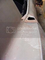
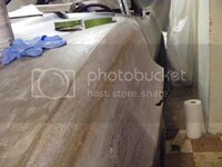
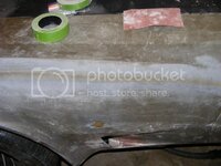
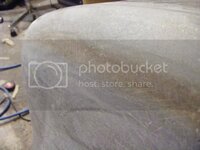
Here the sanded result :

fenderseam9_zps4c43f6c6.jpg


fenderseam8_zps196fc3d1.jpg


fenderseam7_zpsdac046fd.jpg


fenderseam10_zpsf7cc2536.jpg

I'm gonna probably sound cocky here, but I'm damn proud of the result.
A handfull of surface bubble (I couldn't monitor the last layer as I wanted), it feels solid, and the seems are barely noticeable.


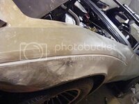
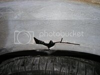
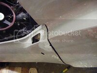
Last pic is a crack in my donor front clip I discovered some time ago. Cracked fiberglass backed by a generous layer of bondo.
I ground into every cracks and removed all the bad fiberglass
fendercrask_zpsee71215b.jpg
 
I too noticed the use of painter tape but didn't really understand it's use. All of my glass work was a total mess compared to what smart people were doing.

Can you explain how to exploit the tape?:confused2:
 
Back
Top