SBG's C3

VetteMod - Corvette Restoration, Modding & Performance Forum

Help Support VetteMod Forum:

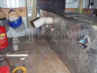
How much do you estimate material cost to be for the complete ss tank?
 
About $140. A comparable tank would cost $1100 built - so you can save some bucks.

Here's the math:

$100 for the stainless flat metal, fittings are really dependant. The 3/8" and 1/2" fittings cost between 3 and 6 bucks each. The fitting I used for the supply was pretty spendy (bulkhead, compression fitting, AN fitting was $26.00) . I have a huge advantage in that my dad owns a shop that builds stainless commercial kitchen equipment so press brake, shear, etc are are just a visit to the parents away (170 miles, one way)... if you had to have a shop do it, it shouldn't cost much for them to chop it out and brake it as long as you give them the dimensions to be cut.

Another alternative, nearby I have a laser shop that does cutting for me, they can be relatively a good cost - however, I also use them for one of my side businesses, so I do get a good-guy discount.

I'd avoid the HVAC shops because this is tougher metal than they're normally used to making; but most metropolis have a shop that does commercial kitchen equipment - and they'd be able to do this.

AN fittings themselves can be kind of spendy - this is who I used
http://www.buyfittingsonline.com/
 
About $140. A comparable tank would cost $1100 built - so you can save some bucks.

Here's the math:

$100 for the stainless flat metal, fittings are really dependant. The 3/8" and 1/2" fittings cost between 3 and 6 bucks each. The fitting I used for the supply was pretty spendy (bulkhead, compression fitting, AN fitting was $26.00) . I have a huge advantage in that my dad owns a shop that builds stainless commercial kitchen equipment so press brake, shear, etc are are just a visit to the parents away (170 miles, one way)... if you had to have a shop do it, it shouldn't cost much for them to chop it out and brake it as long as you give them the dimensions to be cut.

Another alternative, nearby I have a laser shop that does cutting for me, they can be relatively a good cost - however, I also use them for one of my side businesses, so I do get a good-guy discount.

I'd avoid the HVAC shops because this is tougher metal than they're normally used to making; but most metropolis have a shop that does commercial kitchen equipment - and they'd be able to do this.

AN fittings themselves can be kind of spendy - this is who I used
http://www.buyfittingsonline.com/

Some years ago, we noted the price was 1300 bux for a CHEEP island range hood ~30-36" sq. we have a island range, facing the living/dinina area so Linda can not be so isolated when cooking.....

so I went to my welder buddy, and he laid up the dimensions in chaulk on his garage floor, once Linda and I agreed on style, so I went to a metal house and they cut the pieces, he tigged them together, I finished it off, and we hung artsy painted metal decorations on the thing, looks like a million bux, used a attic power vent for the fan.....total cost 400 bux.....

:clap::clap::gurney:
 
As an Amazon Associate we earn from qualifying purchases. Product prices and availability are accurate as of the date/time indicated and are subject to change.
if you are looking for a way to make the new gas cap work in the old hole how about cut out a polished stainless steal ring to go up under the new cap and fill the hole. Why can you not use the stock gas door?
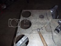
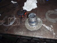
the problem with that route (and I even looked at it again today) is the gas filler would be 6" below the deck to clear the hinge from the gas door.... in the end, I took the easy way out

PB040001.jpg
(for that one person who thinks I get it right the first time)

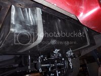
PB040002.jpg
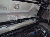
PB040003.jpg
PB040004.jpg

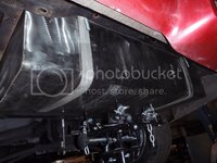
and a framework was made for the tank with some straps
PB040005.jpg

I'll have a couple more pictures of that when I pull the tank down - I had to weld the frame in place, and have to drop the tank to finish weld.
 
if you are looking for a way to make the new gas cap work in the old hole how about cut out a polished stainless steal ring to go up under the new cap and fill the hole. Why can you not use the stock gas door?
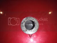
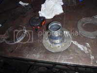
the problem with that route (and I even looked at it again today) is the gas filler would be 6" below the deck to clear the hinge from the gas door.... in the end, I took the easy way out

PB040001.jpg
(for that one person who thinks I get it right the first time)

PB040002.jpg
PB040003.jpg
PB040004.jpg

and a framework was made for the tank with some straps
PB040005.jpg

I'll have a couple more pictures of that when I pull the tank down - I had to weld the frame in place, and have to drop the tank to finish weld.
 
Forgot

Update on the FAST install. I powered up the system today, everything came up and no error codes (woohoo).

However,

it wouldn't be me if there weren't something to bitch about.


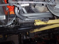
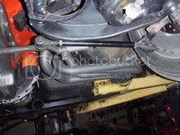
I sent FAST an email at least 3 weeks ago asking about the 02 sensor in the sidepipes. As you may have seen in my post, I've now ground a bit off the ceramic coating to put the sensor in place.


want to guess what FAST said?


"you should put the sensor in 'closer' to the motor"

WTF charlie?

"put the sensor in the leanest pipe"

Anyway, their late take on this is the sensor (at the outside rails) is too far from the motor to get an accurate reading. I say they're full of crap - as there are several OEM designs where the O2 sensor is as far away.... anyway, if I'm wrong, I'll have to drill another hole in the ceramic coating.

So yes, it's an awesome system, and they do fully put the cuss in customer service....
 
Forgot

Update on the FAST install. I powered up the system today, everything came up and no error codes (woohoo).

However,

it wouldn't be me if there weren't something to bitch about.


I sent FAST an email at least 3 weeks ago asking about the 02 sensor in the sidepipes. As you may have seen in my post, I've now ground a bit off the ceramic coating to put the sensor in place.


want to guess what FAST said?


"you should put the sensor in 'closer' to the motor"

WTF charlie?

"put the sensor in the leanest pipe"

Anyway, their late take on this is the sensor (at the outside rails) is too far from the motor to get an accurate reading. I say they're full of crap - as there are several OEM designs where the O2 sensor is as far away.... anyway, if I'm wrong, I'll have to drill another hole in the ceramic coating.

So yes, it's an awesome system, and they do fully put the cuss in customer service....

Is it a wideband sensor? it has an internal haeter, I would test..maybe you are OK. Willing to bet the oem systems you saw had a cat con behind the O2 sensor, those things contribute a lot of heat to the sensor warming up.
 
Forgot

Update on the FAST install. I powered up the system today, everything came up and no error codes (woohoo).

However,

it wouldn't be me if there weren't something to bitch about.


I sent FAST an email at least 3 weeks ago asking about the 02 sensor in the sidepipes. As you may have seen in my post, I've now ground a bit off the ceramic coating to put the sensor in place.


want to guess what FAST said?


"you should put the sensor in 'closer' to the motor"

WTF charlie?

"put the sensor in the leanest pipe"

Anyway, their late take on this is the sensor (at the outside rails) is too far from the motor to get an accurate reading. I say they're full of crap - as there are several OEM designs where the O2 sensor is as far away.... anyway, if I'm wrong, I'll have to drill another hole in the ceramic coating.

So yes, it's an awesome system, and they do fully put the cuss in customer service....

Is it a wideband sensor? it has an internal haeter, I would test..maybe you are OK. Willing to bet the oem systems you saw had a cat con behind the O2 sensor, those things contribute a lot of heat to the sensor warming up.

It's a wideband

no, it wasn't behind the cat converter - OEMs have the second o2 sensor to verify that the cat is working, so it doesn't make much difference about warming up to operating temp - so they use a non-heated, cheaper o2 sensor.... whereas the heated (wideband) needs to be operating as soon as possible so that the motor can operate more efficiently, sooner....

and yes, I am testing it because I've nothing to lose... I still (despite another 3 or 4 emails) haven't received a straight answer from FAST about why it must be closer. Their response has been "air will cause it to read incorrectly".... which, while I know that, isn't true here. There's no air from the motor or from the end of the pipes that would cause a problem. For some reason (and I'm considering while I type), they seem to think the o2 sensor is at the end of the sidepipe, not before the muffler in the collector yet still a fair distance from the motor.
 
The oem rear sensors always have a better heater circuit than the fronts, some people swap rears on the front to get them to warm up better, commonly done w/ header installs. Not all heated are widebands, in fact most are not. C5 etc uses 4 narrow bands, the rears have the better heaters.

On the 502 ramjet here the bung is in the collector but that's right under the rocker panel, a good distance away from the motor, no problem
 
The oem rear sensors always have a better heater circuit than the fronts, some people swap rears on the front to get them to warm up better, commonly done w/ header installs. Not all heated are widebands, in fact most are not. C5 etc uses 4 narrow bands, the rears have the better heaters.

On the 502 ramjet here the bung is in the collector but that's right under the rocker panel, a good distance away from the motor, no problem

I know you're talking generally - however - since the FAST system is advertised with wideband, I think it's safe to assume that it's a wideband O2 sensor.
 
Well you can't put it too far forward as wb sensors do not like getting too hot, 900F is max and if yours runs hotter there are heat sinks available
 
and yes, I am testing it because I've nothing to lose... I still (despite another 3 or 4 emails) haven't received a straight answer from FAST about why it must be closer. Their response has been "air will cause it to read incorrectly".... which, while I know that, isn't true here. There's no air from the motor or from the end of the pipes that would cause a problem. For some reason (and I'm considering while I type), they seem to think the o2 sensor is at the end of the sidepipe, not before the muffler in the collector yet still a fair distance from the motor.

Maybe they are talking about the factory setup where air is pumped into the coverter and the downstream sensor "reads" that?
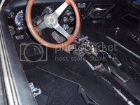
 
and yes, I am testing it because I've nothing to lose... I still (despite another 3 or 4 emails) haven't received a straight answer from FAST about why it must be closer. Their response has been "air will cause it to read incorrectly".... which, while I know that, isn't true here. There's no air from the motor or from the end of the pipes that would cause a problem. For some reason (and I'm considering while I type), they seem to think the o2 sensor is at the end of the sidepipe, not before the muffler in the collector yet still a fair distance from the motor.

Maybe they are talking about the factory setup where air is pumped into the coverter and the downstream sensor "reads" that?

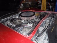
that could be, I took it to mean too close to the end of the exhaust system but at this point I just don't know.

good info, TT, thanks
 
It runs...only made one mistake, I didn't realize the ignition switched lug turned off on starting - so simply moving the plug up to one that didn't turn off and varoom.

a mess, but installed
PB060003.jpg
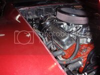
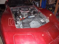
gratuitous engine shots
PB060004.jpg
PB060005.jpg

PB060002.jpg

and I got another scoop... think I'm going with it
PB060001.jpg
PB060006.jpg

O2 sensor seems to work fine. I have a lot of tuning yet to do (especially cold start), but it runs, it drives, and now it's a manual.... all in all, it's good

oh yeah, and my tach works
 
well, I think I can finally at least get it on the ground. I still have to fix one little thing; but other than that (the ignition switch "off" position still leaves the fuel pump on.... and the computer on...

anyway
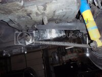
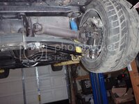
tonight's work was putting in a few suspension bits
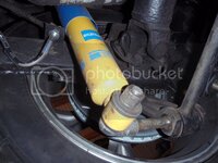
these are notoriously weak - you can even see the bend in the tie rod
PB070001.jpg
PB070008.jpg

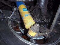
to the rear
these are notorious for bending, clanking, and tearing up poly bushings.
PB070003.jpg
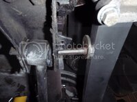
add to this one that the inner bushing seems to be the wrong size, and it would explain some quirky handling (I hope)
of course, it never comes apart easily
PB070005.jpg
PB070006.jpg
PB070007.jpg
 
PB070005.jpg

Is the shock mount installed that way or is it partialy removed from the bearing housing?
 
Should work out ok if you push the shock off the shock mount first ... I moved my brackets to the inside of the arm too, same problem ;)
 
I'm a lazy cuss, so I hate taking things more apart than I have to (of course mostly that means I have to work twice as hard and twice as long... but being lazy ain't easy)
 
hood scoop

Hood scoop
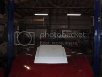
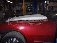
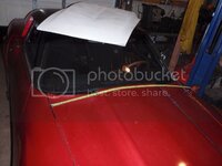
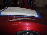
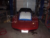
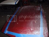
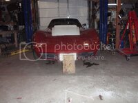
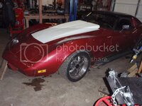
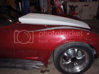
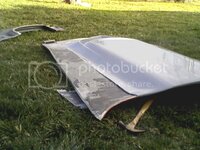
I finally decided on a C4(ish) hood scoop - adds about 1 1/2 " of cowl space without completely blocking the window... so - time to install
PB110001.jpg
Measure, the centerline is absolutely the most important thing you can find
When you have complex shapes, finding the center can be a challenge - sometimes you have to come up with a tool to measure...
PB110002.jpg
what seems to be the center, isn't
PB110003.jpg
center mark the hood
PB110004.jpg
(incidently, this will cure the a$$ and foot marks in the hood - woohoo)
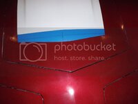
using a calibrated eyeball, I penciled out where the first cuts would be
PB110005.jpg

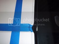
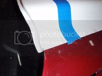
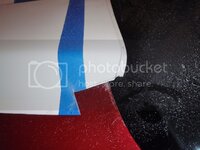
as an aside, I used blue tape because this is a porous fiberglass scoop - if I marked it with anything, it'll suck into the scoop and bleed through when I paint it
and cut
PB110006.jpg
out come the zip screws, and down goes the scoop
PB110007.jpg
looks good, and most importantly it's centered and the horizon is the same on all points
PB110008.jpg
no going back now
PB110009.jpg
I briefly thought of plexiglass in the hole, but no, only hemis look good under glass
PB110010.jpg

so it's cut small, time to trim
PB110011.jpg

took a break and eyeballed what the cold air will look like
PB110012.jpg

looks the same as above, no? actually, no, the scoop is now screwed down where it belongs
PB110014.jpg
side view
PB110015.jpg
PB110016.jpg

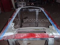
I'm certainly no Dulcich, but I like how it's turning out.... of course, this was the easy part - making it solid is going to be a bit more difficult.... except I'm going to try something a bit new(er), and epoxy a lip to the hood, then epoxy the scoop to the hood. Once that sets up, I'll fill the gap with resin then bondo the top.....
 
Great work! That should work just fine!
Maybe apply a few strips of woven glass from the lip and into the underside of the hood to add a bit of strength? Should be fairly easy.

/Daniel
 
Great work! That should work just fine!
Maybe apply a few strips of woven glass from the lip and into the underside of the hood to add a bit of strength? Should be fairly easy.

/Daniel

Be advised, My hood is a patch on BB style scoop also, and over the years it developed a recurring blister on the left side, about 1/2 was the length of the scoop, took about 8 years to start blistering on the top, I found out after several attempts to fix it, that in fact it was WATER working it's way into the wedge area of the TOPSIDE, from the scoop opening in the rear, the damn water found a minor crack path and so between heat/humiditiy/engine heat, cold down to 17f it forced a way out the surface....

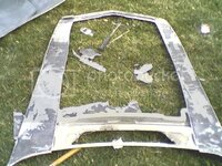
SO eventually I gave it up, and sadly painted the entire hood.....to have it happen yet again.....so this time I want ape **** on it, dug it out again, and this time, cleaned it all up on that wedge V between the pieces of glass on the inside top, but to do that had to remove the center section of the old OEM hood, so out came about 30 lbs of glass, it was very much lighter, anyway.....then I could tip it on it's side, blast out the dirt, using carb/brake cleaner and air jet, then loading up the entire perimeter with fiberglass/ epoxy liquid making damn sure it was full up to the top, THEN I reglassed the hood surface, been fine since.....

I recommend this fix after you get the thing glassed in and before you paint it, ditch the excess glass under the scoop, ALL of it

I set the hood on a couple saw horses, and in a nice breeze shot the glass dust down wind of me, never even got dusty.....using a edge grinder....

:clap:
 
I'm considering using epoxy and light gauge aluminum to make this stay down - heck, they put truck bedsides on with it - it should hold for this.

Denpo - yes, I need the clearance for the next mod something with a little boost :)

Good advice about keeping water away and grinding.... I hate grinding fiberglass. My worst was a fiberglass scoop on a Buick hood - couldn't keep the front point from cracking... argh!
 
Back
Top