
You are using an out of date browser. It may not display this or other websites correctly.
You should upgrade or use an alternative browser.
You should upgrade or use an alternative browser.
Plastic Fantastic 2
- Thread starter SuperBuickGuy
- Start date

Help Support VetteMod Forum:


SuperBuickGuy
Well-known member
I always feel like somebody's watching me

part of today was running the throttle cable....
but first, break every warranty
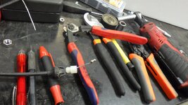
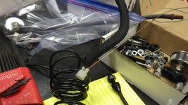
not one thing wasn't modified....
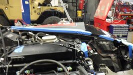
problem 2.... maybe put the radiator vertically?
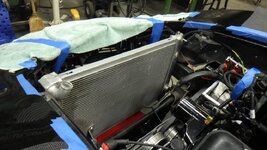
it does give me more room and would provide better cooling, however, it puts the filler below the outlet on the motor
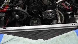
it is above the crossmember
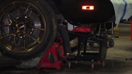
would require pinning the hood
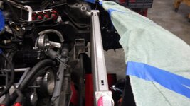
so thinking.
and worked a bit on belt alignment - though I'm waiting on more parts
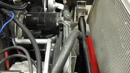
part of today was running the throttle cable....
but first, break every warranty
not one thing wasn't modified....
problem 2.... maybe put the radiator vertically?
it does give me more room and would provide better cooling, however, it puts the filler below the outlet on the motor
it is above the crossmember
would require pinning the hood
so thinking.
and worked a bit on belt alignment - though I'm waiting on more parts

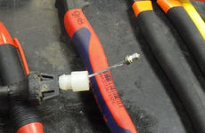
Did you crimp the cable stop?
SuperBuickGuy
Well-known member
I chopped it off the GM cable and installed it on the Lokar cable (which already was crimped)

phantomjock
Well-known member
I gotta finish the front suspension first... Brakes arrive this next weekend, uprights getting finished at the machine shop. Pushrod shocks and springs are in. The air box for my radiator has been done for a few years. Just not installed - too much in the way.You mentioned a vertical rad. I always wanted to investigate using a short thick radiator that leaned forward, with electric fans ducted out the hood. I think I've seen photos somewhere.
Pics and updates starting soon, I PROMISE!


![Pampers Sensitive Baby Wipes, Clinically Proven, Fragrance Free, Unscented, Water Based, Hypoallergenic, Multi-Use, Hand Wipes 336 Wipes Total (6X Flip-Top Packs) [Packaging May Vary]](https://m.media-amazon.com/images/I/41KLBHu9CAL._SL500_.jpg)





As an Amazon Associate we earn from qualifying purchases. Product prices and availability are accurate as of the date/time indicated and are subject to change.
SuperBuickGuy
Well-known member
lots of years ago, at the Corvette Swap meet (near Seattle), the 'show' portion had a really track prepped C3 with a vertical radiator. He used a shorter radiator - cannot remember what he said he used (RX7?).... I dunno if I'm going to go that far because I already have cooling issues, my last thought was a LS7 Z06 radiator would be sufficient. It wasn't.You mentioned a vertical rad. I always wanted to investigate using a short thick radiator that leaned forward, with electric fans ducted out the hood. I think I’ve seen photos somewhere.

bobs77vet
Well-known member
sorry to hear about your health scare i hope it resolves its self favorably
SuperBuickGuy
Well-known member
so far so good...sorry to hear about your health scare i hope it resolves its self favorably
SuperBuickGuy
Well-known member
State of the state update
phantomjock
Well-known member
Nice Update. Good format.
What was the camera? Looks better than a phone (more stable and landscape format.)
Thanks for the full tour - makes me even more jelous of the space.
But, if I had it, it would be chocker as well.
Cheers - Jim
What was the camera? Looks better than a phone (more stable and landscape format.)
Thanks for the full tour - makes me even more jelous of the space.
But, if I had it, it would be chocker as well.
Cheers - Jim
SuperBuickGuy
Well-known member
the camera is a Ricoh WG-80.... I'm not in love with it but it does have its moments.Nice Update. Good format.
What was the camera? Looks better than a phone (more stable and landscape format.)
Thanks for the full tour - makes me even more jelous of the space.
But, if I had it, it would be chocker as well.
Cheers - Jim
I am so blessed with this shop, words can't describe it.
Really nice shop and so well organized. Considering how many projects you have going on, that's remarkable. I spend as much time looking for stuff than I do working on stuff (with one project).
SuperBuickGuy
Well-known member
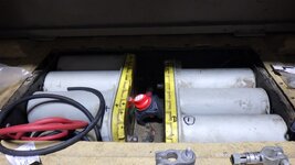
The FJ40. Last night I was wiring in a double battery set up. I had the last piece - a negative terminal top post to stud converter sitting right in front of me. Spent an hour, never found it. Will go buy another today.... the worst part of the shop, in the last shop I knew where everything was (mostly because I'd put it there)... this one I'm hoping this summer I can drag all the cars out then start organizing... probably won't, but it is in my thoughts.Really nice shop and so well organized. Considering how many projects you have going on, that's remarkable. I spend as much time looking for stuff than I do working on stuff (with one project).
middle of the picture.... no idea where it went
SuperBuickGuy
Well-known member
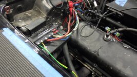
solid state relay connected and operational
and now the boring part
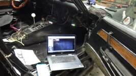
I have lots of questions about how to make the spark system - so that will be a phone call to Holley tomorrow.
and now the boring part
I have lots of questions about how to make the spark system - so that will be a phone call to Holley tomorrow.
SuperBuickGuy
Well-known member
working, again, on the core support
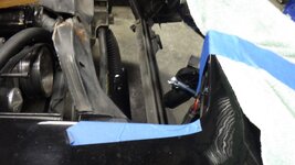
note on Paul's car, there's actually some room between the condenser and the headlight cannisters
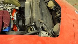
I think I can gain about 3" total redoing the support (move it towards the nose and also down
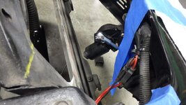
the key here is this, the air cleaner is going to be a copy of what the C5 Z06 looks like
working, again, on the core support
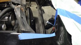
note on Paul's car, there's actually some room between the condenser and the headlight cannisters
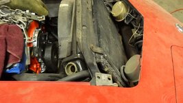
I think I can gain about 3" total redoing the support (move it towards the nose and also down
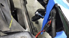
the key here is this, the air cleaner is going to be a copy of what the C5 Z06 looks like
note on Paul's car, there's actually some room between the condenser and the headlight cannisters
I think I can gain about 3" total redoing the support (move it towards the nose and also down
the key here is this, the air cleaner is going to be a copy of what the C5 Z06 looks like
working, again, on the core support
note on Paul's car, there's actually some room between the condenser and the headlight cannisters
I think I can gain about 3" total redoing the support (move it towards the nose and also down
the key here is this, the air cleaner is going to be a copy of what the C5 Z06 looks like
bobs77vet
Well-known member
the state of the shop is good!!!!
SuperBuickGuy
Well-known member
Back to this, not much to report. I talked to Holley today so I could figure out how to program the ignition...
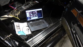
I could probably start it... but I need to verify several things like sensors and timing so it's going to wait a bit
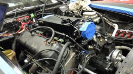
I could probably start it... but I need to verify several things like sensors and timing so it's going to wait a bit
phantomjock
Well-known member
Fire it up Christmas morning!
You'll know if you've been Bad - or Good!
Fingers crossed.
You'll know if you've been Bad - or Good!
Fingers crossed.
SuperBuickGuy
Well-known member
Come on Holley.. you could at least expand it to the entire page.... try reading this. With a magnifying glass... still isn't clear. thankfully it's online but this is bs
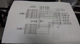
what am I going on about... this
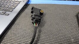
more directly this.... I have no idea what this plug is (and don't say Delphi, it ain't)
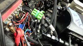
the correct order
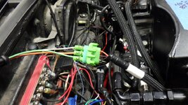
green plug bad, green plug gone.... warranty voided
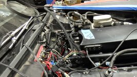
and installed
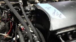
tomorrow will be the big day to test sensors... have one more to install (at least I think only one more)...
what am I going on about... this
more directly this.... I have no idea what this plug is (and don't say Delphi, it ain't)
the correct order
green plug bad, green plug gone.... warranty voided
and installed
tomorrow will be the big day to test sensors... have one more to install (at least I think only one more)...
Holley's schematics include some mistakes also. Just to keep it interesting.
SuperBuickGuy
Well-known member
grand, can't wait to find them.... Merry Christmas to all (except Holley)Holley's schematics include some mistakes also. Just to keep it interesting.
did I mention that they've sent me a second programmer and it doesn't work either?
SuperBuickGuy
Well-known member
Sensors work, fuel line leaks (well, after I swapped the lines)
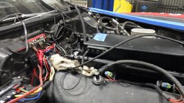
remove sensor for now
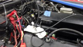
start on accessories
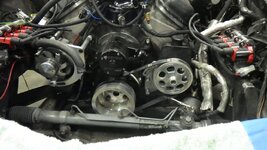
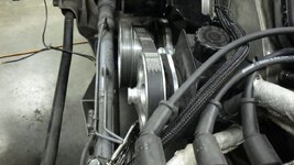
It does pop.... which means I have spark and fuel, just not at the right time. Add to this that I zero lashed the rockers - and I have a couple steps before it truly makes sweet noise (like putting a cooling system together and making the accessories work).
I have questions about spark control... and I need to spend some quality time understanding what I need to do.... but still, it will run.
Merry Christmas
remove sensor for now
start on accessories
It does pop.... which means I have spark and fuel, just not at the right time. Add to this that I zero lashed the rockers - and I have a couple steps before it truly makes sweet noise (like putting a cooling system together and making the accessories work).
I have questions about spark control... and I need to spend some quality time understanding what I need to do.... but still, it will run.
Merry Christmas
phantomjock
Well-known member
I'm late - so; hope you had a Merry Christmas! Also - plan on having a Happy New Year!
Cheers - Jim
Cheers - Jim
SuperBuickGuy
Well-known member
My ADD on full display
Langmuir cnc plasma
I bought this years ago (2015 ish) never really used it because I rarely copy parts.... and it is kind of time consuming for one-offs. With that said, it also didn't have a Z-axis control - which leads to a challenge getting parts to look good as the plasma varies in height over the material. ... my wife has some parts that need to be cut out, so it was a good 'excuse' to get it updated.... so here we go.....
mostly it's been a computer stand
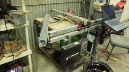
out with the old
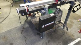
but given how 'old' it is, they sent an entire, new computer... which also means I have an x/y axis control (read mill) that is now homeless
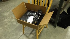
as with anything else, break every warranty... this time, the Z-axis parts need to be installed in the new controller
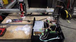
as an aside, it's amazing how close I got to making one from scratch.... all the parts inside I know and know what they do....
you can tell that it's replaced because it's less dusty
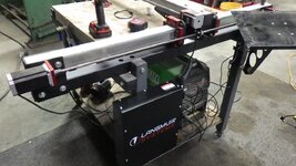
need to run it in, but ready to go
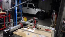
Langmuir cnc plasma
I bought this years ago (2015 ish) never really used it because I rarely copy parts.... and it is kind of time consuming for one-offs. With that said, it also didn't have a Z-axis control - which leads to a challenge getting parts to look good as the plasma varies in height over the material. ... my wife has some parts that need to be cut out, so it was a good 'excuse' to get it updated.... so here we go.....
mostly it's been a computer stand
out with the old
but given how 'old' it is, they sent an entire, new computer... which also means I have an x/y axis control (read mill) that is now homeless
as with anything else, break every warranty... this time, the Z-axis parts need to be installed in the new controller
as an aside, it's amazing how close I got to making one from scratch.... all the parts inside I know and know what they do....
you can tell that it's replaced because it's less dusty
need to run it in, but ready to go
SuperBuickGuy
Well-known member
it does start-ish... timing is way late, but the good news is fuel and spark IS happening - so now it's just a matter of fine tuning.... oh, and I didn't send the intake into low earth orbit.... so win, win
also got the belts lined up
3/8" spacers
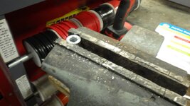
installed
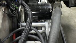
and here it is
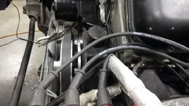
had to drill out the power steering spacers - still not thrilled with how wobbly it is - if it's noisy, I'll have to make a bracket
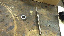
also got the belts lined up
3/8" spacers
installed
and here it is
had to drill out the power steering spacers - still not thrilled with how wobbly it is - if it's noisy, I'll have to make a bracket
SuperBuickGuy
Well-known member
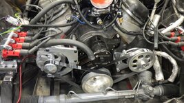
finished the belts.... even got the right belts the first time...
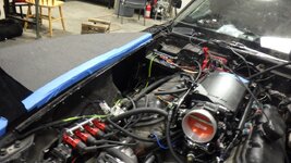
then made a hole
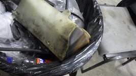
to replace the leaky reservoir
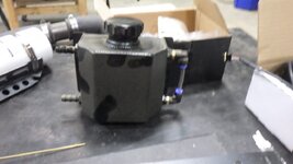
with one that doesn't leak
in other news, for the first time in my existence I had a truck come through with too small of a carb.
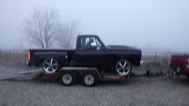
backstory, guy on a neighbors page was having trouble with his 406 sbc. wouldn't run over 3000 rpm and running extremely rich..... well, if you put a 650 carb on a motor that needs 700 cfm minimum, it'll pull fuel in its search for air. Loaned him an 870 that I had on the Buick.... thing runs hard... he's quite pleased, figured I better get at least one good deed in in 2023.... beautiful truck, it's purple.
and the Corvette. It's popping like it wants to start - but not triggering my timing light - which suggests it's just fuel detonating with compression... so much of the rest of my day has been doing a deep dive on what I need to do to make it roar. but alas, I'm always breaking trail - and this is no different.
then made a hole
to replace the leaky reservoir
with one that doesn't leak
in other news, for the first time in my existence I had a truck come through with too small of a carb.
backstory, guy on a neighbors page was having trouble with his 406 sbc. wouldn't run over 3000 rpm and running extremely rich..... well, if you put a 650 carb on a motor that needs 700 cfm minimum, it'll pull fuel in its search for air. Loaned him an 870 that I had on the Buick.... thing runs hard... he's quite pleased, figured I better get at least one good deed in in 2023.... beautiful truck, it's purple.
and the Corvette. It's popping like it wants to start - but not triggering my timing light - which suggests it's just fuel detonating with compression... so much of the rest of my day has been doing a deep dive on what I need to do to make it roar. but alas, I'm always breaking trail - and this is no different.
SuperBuickGuy
Well-known member
this is supposed to be in the help? area of the software.... it's not working, so here it is for me to reference tomorrow...
ah winning... instructions for tomorrow...
1.0 CRANK SENSOR SETUP
1.1 Ignition Reference Setup – "one pulse per fire" trigger, Magnetic Pickup
The following shows how to setup the crank signal for a "one pulse per fire" RPM input using either a Magnetic pickup crank trigger or distributor.
A "one pulse per fire" trigger means there is one sensor pulse for every cylinder firing (on a V8 this would be a 4 pulse crank trigger or a 8 pulse trigger in the distributor).
NOTE: In the software, the Sensor Type should be setup as "Magnetic".
1. Note the Ignition Reference Angle set in the software. This is typically set to a value that is 10° more than the highest timing you will run.
Do NOT set it higher than 75°. 60° is a common value. 60° is used for an example here.
2. Turn the engine over so that it is at the Ignition Reference Angle. For this example it would be 60° BTDC on cylinder # 1
The timing pointer should be indicating 60° BTDC on the crank.
3. Align/turn the crank trigger or distributor so that the sensor is perfectly inline with the trigger.
• For a Magnetic pickup crank trigger, this means the pickup and a magnet should be inline.
• For a Magnetic pickup distributor, this means having one of the reluctor teeth line up with the Magnetic pickup.
4. Tighten every thing up.
5. If you are not using a cam sync (if you are, continue to section 2.1), everything should be set close enough to start the engine.
It is recommended that you disconnect the injectors and crank the engine over.
Look at the timing with a timing light. It should be firing at the cranking timing value shown on the data monitor.
If it is off a few degrees, you can move the pickup slightly, or change the Ignition Reference setting to sync things up.
If you change the Ignition Reference value, note that you must cycle the ignition power for it to take affect.
and
2.1 Cam Sync setup when using a "one pulse per fire" crank input
For a "one pulse per fire crank" signal (e.g. a 4 pulse crank trigger on a V8), the cam sync signal must occur in a specific range to properly identify which cylinder is cylinder # 1 If this is not done properly, individual cylinder trims will not be performed on the correct cylinder, or worse, if using individual coils, the wrong cylinder will be fired, potentially damaging the started, flexplate, or worse.
The best way to determine the proper range is by using the following basic formula to determine the crank angle range that the cam identity can occur. An example is give afterwards along with a table that has certain combinations already calculated.
Cam sync location (degrees BTDC #1) = "Ignition Reference Angle" + "A" + ("A" / 2)
"Ignition Reference Angle" = Taken from Crank Sensor Setup in software
"A" = Angle Between Crank Pulses (crank degrees between triggers on the crank sensor)
"A" for a 8 cylinder = 90°
"A" for a 6 cylinder = 120°
"A" for a 4 cylinder = 180°
Using the formula above, plug in the "Ignition Reference Angle" you are using and the proper "A" value depending on the number of engine cylinders.
The location calculated is the "ideal" location and can vary +/- 30° or possibly more.
If you are out of this range contact Holley Tech Service for options.
Example - 8 cylinder with a Ignition Reference Angle of 60°
Cam Sync Location = 60 + 90 + 90/2 = 195 degrees BTDC #1
Cam Sync Location = 60 + 90 + 45 = 195 degrees BTDC # 1
195° would be the centrally "perfect" location for this specific example.
However, this location can vary by +/- 30 degrees from this nominal target value with no issue.
Number of Cylinders Ignition Reference Angle Cam Trigger Location Range (BTDC #1)
4 60 330 +/-30 degrees
6 60 240 +/-30 degrees
8 60 195 +/-30 degrees
ah winning... instructions for tomorrow...
1.0 CRANK SENSOR SETUP
1.1 Ignition Reference Setup – "one pulse per fire" trigger, Magnetic Pickup
The following shows how to setup the crank signal for a "one pulse per fire" RPM input using either a Magnetic pickup crank trigger or distributor.
A "one pulse per fire" trigger means there is one sensor pulse for every cylinder firing (on a V8 this would be a 4 pulse crank trigger or a 8 pulse trigger in the distributor).
NOTE: In the software, the Sensor Type should be setup as "Magnetic".
1. Note the Ignition Reference Angle set in the software. This is typically set to a value that is 10° more than the highest timing you will run.
Do NOT set it higher than 75°. 60° is a common value. 60° is used for an example here.
2. Turn the engine over so that it is at the Ignition Reference Angle. For this example it would be 60° BTDC on cylinder # 1
The timing pointer should be indicating 60° BTDC on the crank.
3. Align/turn the crank trigger or distributor so that the sensor is perfectly inline with the trigger.
• For a Magnetic pickup crank trigger, this means the pickup and a magnet should be inline.
• For a Magnetic pickup distributor, this means having one of the reluctor teeth line up with the Magnetic pickup.
4. Tighten every thing up.
5. If you are not using a cam sync (if you are, continue to section 2.1), everything should be set close enough to start the engine.
It is recommended that you disconnect the injectors and crank the engine over.
Look at the timing with a timing light. It should be firing at the cranking timing value shown on the data monitor.
If it is off a few degrees, you can move the pickup slightly, or change the Ignition Reference setting to sync things up.
If you change the Ignition Reference value, note that you must cycle the ignition power for it to take affect.
and
2.1 Cam Sync setup when using a "one pulse per fire" crank input
For a "one pulse per fire crank" signal (e.g. a 4 pulse crank trigger on a V8), the cam sync signal must occur in a specific range to properly identify which cylinder is cylinder # 1 If this is not done properly, individual cylinder trims will not be performed on the correct cylinder, or worse, if using individual coils, the wrong cylinder will be fired, potentially damaging the started, flexplate, or worse.
The best way to determine the proper range is by using the following basic formula to determine the crank angle range that the cam identity can occur. An example is give afterwards along with a table that has certain combinations already calculated.
Cam sync location (degrees BTDC #1) = "Ignition Reference Angle" + "A" + ("A" / 2)
"Ignition Reference Angle" = Taken from Crank Sensor Setup in software
"A" = Angle Between Crank Pulses (crank degrees between triggers on the crank sensor)
"A" for a 8 cylinder = 90°
"A" for a 6 cylinder = 120°
"A" for a 4 cylinder = 180°
Using the formula above, plug in the "Ignition Reference Angle" you are using and the proper "A" value depending on the number of engine cylinders.
The location calculated is the "ideal" location and can vary +/- 30° or possibly more.
If you are out of this range contact Holley Tech Service for options.
Example - 8 cylinder with a Ignition Reference Angle of 60°
Cam Sync Location = 60 + 90 + 90/2 = 195 degrees BTDC #1
Cam Sync Location = 60 + 90 + 45 = 195 degrees BTDC # 1
195° would be the centrally "perfect" location for this specific example.
However, this location can vary by +/- 30 degrees from this nominal target value with no issue.
Number of Cylinders Ignition Reference Angle Cam Trigger Location Range (BTDC #1)
4 60 330 +/-30 degrees
6 60 240 +/-30 degrees
8 60 195 +/-30 degrees
SuperBuickGuy
Well-known member
It runs... that math for the cam sync? utter and complete BS. It DOES need to be set in advance of the crank signal - and Holley recommends at least 10 degrees - but that 195 degree stuff. nope.
Similar threads

- Replies
- 4
- Views
- 5K

- Replies
- 4
- Views
- 2K


