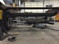
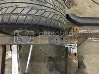
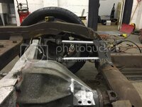
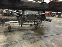
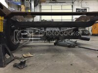
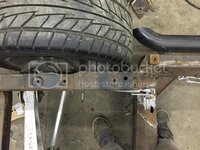
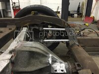
C3/4/5 frankenstein frame

VetteMod - Corvette Restoration, Modding & Performance Forum

Help Support VetteMod Forum:

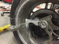
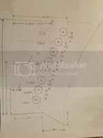
Here is a modification I have been planning on testing for some time - just haven't gotten around to it. It is a way to eliminate the adverse C-3 rear roll steer problem without making major modifications to the car's frame. One solution is with the C-4 suspension (or Guldstrand mod), but that requires surgery to the frame at the front trailing arm mount, and the forward links are shorter than I would like to see. The forward links provide an "instant center" of motion (at the intersection of their extended centerlines), but unlike a 4-link set-up on a solid axle, do not transmit torque from the axle to the chassis. The C-4 forward links merely transmit forward force through the instant center, although they do transmit braking torque since the caliper is mounted to the bearing support. The forward links of the C-4 suspension can therefore be replaced with a "ladder bar" that uses the original C-3 trailing arm forward pick-up point. A C-3 trailing arm can be modified (if you prefer the C-3 bearing configuration) to do the same thing. See the attached "crude" sketch, for which I apologize.
Finally, a toe control rod can then be added to either the C-4 upright or to a modified C-3 trailing arm as shown in the sketch. Note: you cannot simply add a toe control rod to the back of an unmodified, rigid C-3 trailing arm because the suspension will bind (too many things swinging in different arcs). All that remains is to add a pick-up fixture, either on the differential or the differential cross-member, to pick up the inboard end of the toe control rod. I have a couple of extra C-3 trailing arms and I will build an example to test.

View attachment 1814

Hey Pappy, we're on the same wavelength. :thumbs: Prior to putting in the C4 stuff I kicked around a modified trailing arm similar to your drawing. Went the C4 knuckle route though when I realized I had enough spare C4 stuff laying around from my street rod suspension conversion, but still had to make a bracket to adapt the toe arms to the C3 differential cover.
 
The apparent "trick" to both cars is minor modifications to the front control arm pick-ups, excellent caster gain with fairly high travel, big tires (315s front and rear), and superb shock valving.
Care to share more details on the front control arms? Are they doing more than offsetting the uppers for more caster? Are they relocating upper and lowers?

Looks like they are going for more caster GAIN during suspension travel - spacing the front of the lower control arm down (putting a spacer block between the front of the control arm shaft and the frame), which causes more caster gain as the suspension compresses. Danny Popp's car had tubular lower control arms on it at the Goodguy's shoot-out, not the stamped lowers he had on it before. It also looks like they are using very high quality, adjustable shocks and, on the autocross, are using a slow rebound to pin the nose down through most of the corner. Watching Brian's car from the front, there is very little roll on corner entry and both front tires seem to be doing their fair share of the work. Brian in particular is dealing with a lot of scrub radius, which tells me he is probably compensating with lots of caster - it doesn't seem to be hurting him. Another thing I noticed, with the 200 tread wear rated tires are the very wide rims compared to tread width - not wide tires on too-narrow rims. I'll guess that some research has been done to optimize the tire contact patch with that tire. These are just observations on my part and do not reflect anything I was told by either driver. Oh, I almost forgot, the steering appeared to be very quick with the Borgeson steering boxes - so quick that during tight corners you could see the front wheels "twitching" like a dirt sprint car in response to the drivers' steering inputs. Looked perfect for a tight autocross track.
So the caster gain on compression would equate to camber gain on hard cornering but no camber gain on hard braking, correct?
 
"So the caster gain on compression would equate to camber gain on hard cornering but no camber gain on hard braking, correct?"

That is essentially correct - very minimal camber gain on compression (less that 1/4 degree per inch of compression), but lots of camber gain as the wheels are turned due to the high caster. I end up with about 3 degrees of negative camber on the outside and about 2 degrees of positive camber on the inside with 25 degrees of turn and at 4 inches of compression. All good!

Pappy
 
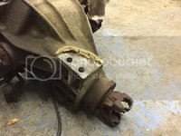
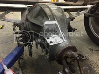
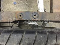
Minor progress... Cut the top of the C-channel mount off. Even after this I think Im still going to have a little interference with the storage compartments
Before:
C440B9FF-F355-4463-8C5C-58691E51C769_zpsjlq5rd05.jpg

After:
I tried to maintain the center rib as best I could.
F337D351-1036-4A1C-8203-B593A59CF104_zps2a4hj6ee.jpg

My stock diff was solid mounted to the frame at the sombreros and the pinion... Now this one has the rubber bushings on the batwing and I would think Im now going to lose a pretty significant 'crossmember' in my frame. Not sure if I feel comfortable using a solid bushing in the batwing mounts. Maybe poly? Opinions? Do the C4 guys change these out?
 
Well, at least you have a welded steel crossmember behind the batwing. My '80 has only the batwing diff with rubber mounts to connect the rear kickup frame members so i assume your setup is still stronger than a '80-'82 C3 frame which has no extra steel crossmember in the back, only a flimsy steel strip to support the gas tank.

IMG_5787Small_zpsab73b97b.jpg

I would love to weld in a '79< steel crossmember behind the batwing in my '80. Given the fact i have stripped my Vette to the bare frame i might even do so.

Great topic to follow! :thumbs:
 
Last edited:
Wow I didnt know the later vettes did not have that crossmember... Yikes!

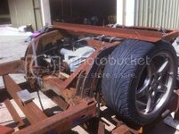
A lot of head scratching went on in the shop today... Here is where packaging all of this stuff turns into a nightmare.
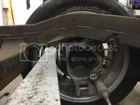
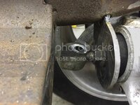
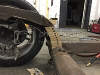
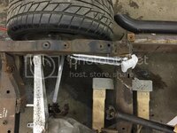
This is ride height. The upper forward link is going to hit the underside of the frame rail. Im going to have to clearance the underside of the frame rail about 2.5" to give me 2.5" of compression.
B3DC363B-5C4F-4F70-A439-4D3538FA1B2D_zpsejbvsgll.jpg

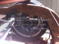
the toe control rod is also very close to the batwing, but it should clear if I mount a rod end to the bottom rather than the top.
4360D808-0ECB-4781-96B3-C64DBBCACE4D_zpsfm3gpvk4.jpg

The spring perch and sway bar mount were interfering with the frame and the batwing, so off they go. Im likely going to trim a bit more off the back side where the perch was. This is a rough cut
90D163B3-FFEC-4A25-BF5F-7C739A9F3D12_zpstsyvaa6k.jpg
5162939C-C59B-43B2-9C02-B673C6B4AB04_zps4ti8eruc.jpg

Since the original swaybar mount is gone, I think Im going to use the lower shock mount as my new swaybar attachment point and run the swaybar along the crossmember before the frame kicks up. Im not sure where Im going to mount a coilover in here since using the stock lower shock mount would put the top of the shock inside my storage compartments.

23BA4560-B86F-4973-89EF-83B4A8AEB697_zpsnliapk84.jpg

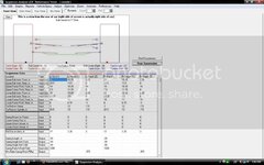
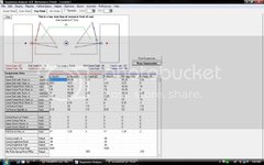
Heres what I have so far into the suspension analyzer...
This is at my ride height and diff placement. I think I might move the diff up another inch or so. The frame mounts for the forward links are just dummy numbers for now until I can see where I can really put them. I would like to keep the misalignment (angled in) if that isnt going to cause me any problems.
screenshot1pt_zps65cdaf36.jpg
screenshot2pt_zps8d4bb5c1.jpg

Also after doing a bit of reading in the C4 section of CF it seems as if the D44 batwing is a bit weaker then the early D36 batwings. I see someone makes an adapter plate to mate the D36 wing to the D44 chunk but I dont really like the ovaling of the holes to get the bolts to line up. Can anyone confirm that these batwings are cast and not forged? Im going to have some braces welded in (assuming its not forged) so I feel a bit more comfortable solid mounting it and making it a structural member of the frame
 
As an Amazon Associate we earn from qualifying purchases. Product prices and availability are accurate as of the date/time indicated and are subject to change.
Vette 427
That wheel looks like a 17" rim , so I'm thinking this car is going to be very low at the ride hight you have set up.
I have a number of things worked out for this swap but my car is set up at 1" lower than stock?
What is the underside of the side frame rail to ground dimension.
Bfit
 
Last edited:
photos

Picturev006.jpg


Picturev005.jpg

two photos of the swap I'm doing
frame is set at 6 3/4" from ground level to bottom of frame.
I have purchased a later Viper diff to see if it will work better than using the C4 Dana 44 for mounting reasons.
Bfit
 
Last edited:
Im not at my shop currently so I dont know what mine is at that position. Im measuring frame height at the top of the #4 and #6 body mounts. My ride height puts them both at 10.5". This should put my rear fender lip at right around 27.5"

My current wheels are 18" with a 27" tall rear tire. I am pushing the track width out about 1" from stock C3. Im worried if I push the diff up any higher it will hit the floor, and I really dont want to cut that up. Im going to try and work out the other suspension link pickup points to compensate for the halfshafts being angled up. We'll see if I can get that to work or not. The screen shots I posted are just the stock pickup points as it sits now. I havent messed with it yet to get my desired geometry.

Keep us posted on the Viper diff... Id be interested to see how that works out!

EDITED
 
Last edited:
My frame measures 12 1/2' from ground to the top of the body mounts on the side rails, mounts 2 and 3
I have 7" from bottom of frame to ground .
I will set suspension travel at total 4" and use Ridetech TQ shocks,

one of my other C3's ( 70 Model ) measures 28" to the lip on the rear and 26" to lip on the front .
I have 6 3/4' ground to the bottom of the frame just in front of the rear wheel
Bfit
 
Last edited:
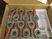
Got my rod ends in today and my hex tube stock should be here tomorrow.
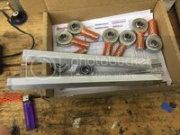
I went with FK bearings RSMX series. .625" hole and 3/4-16 thread with a PTFE liner. They have a 40,000 radial load. Ill be using these on everything except the toe control. The hex tube is 6061 aluminum 1" with a .5" ID. I got 6 feet, which should let me do one side of the car with a bit to spare.
A9628190-BB1B-40E0-9CC6-8310366C31C1_zpshpy9lli1.jpg
 
Small progress today...
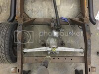
Got the frame rough cut for clearancing the trailing rods. With these on the inside of the entire frame rail (instead of in the rail) Ill be able to box and triangulate it with some tubing (credit to 69427 for the triangulation idea)
C087A4DB-2FF2-4E36-96DD-9BD8F2FBE2B3_zpsrbt87nr6.jpg

BACD671A-7FFF-4643-9FBA-62C954F1BB24_zpshgwzddpe.jpg

Cut some of my hex tubing... Anyone ever bore tubing out on a drill press? Or is this better suited for a lathe?
955C75E0-BE21-43F5-AB7B-723961520157_zpsj5sctsjw.jpg

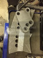
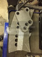
And got these sent off to be laser cut. Please excuse the sloppy drawing :blush:
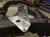
This is the camber rod mount on the diff:
B778FA27-65FD-4F9E-B02F-766AAF077275_zps3mxdnf2g.jpg

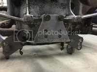
And the trailing link brackets:
D70B2FFC-F42A-438B-9B6A-CE2F35523942_zpso3mvmdk8.jpg
 
Got my brackets in the mail today :bounce:

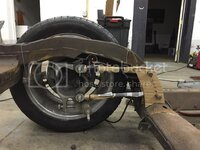
The frame is at ride height +/- .25" in all these pics
0B1373CA-F3F4-442A-9216-726C2268BF6C_zpsqctv4sjl.jpg

510F8327-9F1A-4188-AA61-8CA656D8C44E_zps0l1vrrym.jpg

ACEA2CF7-B3FB-40D4-93BF-357546A34A3E_zpsbqfu9rca.jpg

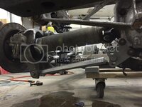
A little more accurate positioning of the trailing links in relation to the frame rail:
11591ECC-E0F1-49B8-8C87-0F0635A9A53A_zpshgdtzaa4.jpg

I cut out the entire side of the kickup... Plenty of rust forming between the double wall sections :twitch:
F69B90AC-4312-4C4D-BC28-0BD67B3402DB_zpsbpleglt7.jpg

Not sure how Im going to make the trailing link bolts accessible to change position. As of now, Im thinking of putting an access door in the kickup and pull bolts from that side. I will be putting the triangulation brace back so that makes it difficult to pull the upper bolt all the way out from that end. Other ideas?

Also, the tubing lengths are just estimates until I can finalize everything. then I will account for jam nuts ;)
 
Last edited:
"I will be putting the triangulation brace back so that makes it difficult to pull the upper bolt all the way out from that end. Other ideas?"

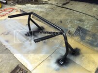
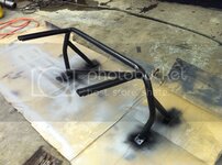
Instead of the triangle braces, maybe a 6 point roll bar.
 
Got my brackets in the mail today :bounce:

The frame is at ride height +/- .25" in all these pics
0B1373CA-F3F4-442A-9216-726C2268BF6C_zpsqctv4sjl.jpg

510F8327-9F1A-4188-AA61-8CA656D8C44E_zps0l1vrrym.jpg

ACEA2CF7-B3FB-40D4-93BF-357546A34A3E_zpsbqfu9rca.jpg

A little more accurate positioning of the trailing links in relation to the frame rail:
11591ECC-E0F1-49B8-8C87-0F0635A9A53A_zpshgdtzaa4.jpg

I cut out the entire side of the kickup... Plenty of rust forming between the double wall sections :twitch:
F69B90AC-4312-4C4D-BC28-0BD67B3402DB_zpsbpleglt7.jpg

Not sure how Im going to make the trailing link bolts accessible to change position. As of now, Im thinking of putting an access door in the kickup and pull bolts from that side. I will be putting the triangulation brace back so that makes it difficult to pull the upper bolt all the way out from that end. Other ideas?

Also, the tubing lengths are just estimates until I can finalize everything. then I will account for jam nuts ;)

Just typing without benefit of looking under my car, but can you drill something like a 1 1/2" hole in the frame upright outward from the upper bolt (and then weld in some tubing to seal and strengthen the hole) so you have a tunnel to install the bolt from the outside?
 
"I will be putting the triangulation brace back so that makes it difficult to pull the upper bolt all the way out from that end. Other ideas?"

Instead of the triangle braces, maybe a 6 point roll bar.

Already done. The stiffer the frame, the better :bounce:

Just typing without benefit of looking under my car, but can you drill something like a 1 1/2" hole in the frame upright outward from the upper bolt (and then weld in some tubing to seal and strengthen the hole) so you have a tunnel to install the bolt from the outside?

Not a bad idea... it would have to be open to access all the holes though.

I have an idea in progress. Going to leave the frame rail solid and weld a piece with threads on the inside of the bracket. Then Im hoping to fab some kind of triangulation piece that will allow me to remove the top bolts via some dimple dies or something similar. Thats the plan at least :hunter:
Lots more stuff in the "idea stage"...
I have a C5 tubular swaybar that I want to try to make work in the rear with some custom adjustable arms, RideTech coilovers are on the way so I can get the upper mount fabbed up, custom toe rod bracket to lower the tie rods so I can move them to the underside of the spindle is also on its way here. Its just too damn cold to get motivated to do anything. :goodnight:
 
"I will be putting the triangulation brace back so that makes it difficult to pull the upper bolt all the way out from that end. Other ideas?"

Instead of the triangle braces, maybe a 6 point roll bar.

Already done. The stiffer the frame, the better :bounce:

Just typing without benefit of looking under my car, but can you drill something like a 1 1/2" hole in the frame upright outward from the upper bolt (and then weld in some tubing to seal and strengthen the hole) so you have a tunnel to install the bolt from the outside?

Not a bad idea... it would have to be open to access all the holes though. ??

I have an idea in progress. Going to leave the frame rail solid and weld a piece with threads on the inside of the bracket. Then Im hoping to fab some kind of triangulation piece that will allow me to remove the top bolts via some dimple dies or something similar. I'm not following your drift here. Thats the plan at least :hunter:
Lots more stuff in the "idea stage"...
I have a C5 tubular swaybar that I want to try to make work in the rear with some custom adjustable arms, RideTech coilovers are on the way so I can get the upper mount fabbed up, custom toe rod bracket to lower the tie rods so I can move them to the underside of the spindle is also on its way here. Its just too damn cold to get motivated to do anything. :goodnight:

I was assuming, due to the brace angle, that only the top one or two locations were too tight to install the bolt from the inside, and that the rest would be accessed from the interior area.
 
"Already done. The stiffer the frame, the better "

A horizontal bar in the main roll bar for seat belts would probably eliminate the need for triangular braces. Or, a second horizontal bar lower tying the kick ups to each other.

Just a thought.
 
I was assuming, due to the brace angle, that only the top one or two locations were too tight to install the bolt from the inside, and that the rest would be accessed from the interior area.

Ill retract my comment "not a bad idea" and say that is a much better idea. I kept thinking that all the bolts had to face the same direction. If my current plan doesnt work out, I think this is the way to go :beer:
 
"Already done. The stiffer the frame, the better "

A horizontal bar in the main roll bar for seat belts would probably eliminate the need for triangular braces. Or, a second horizontal bar lower tying the kick ups to each other.

Just a thought.

I am potentially losing my previously solid mounted diff as a frame brace (not sure if I will be able to make the aluminum batwing/diff a stressed frame member yet) so Im trying to retain as much rigidity as I can here by keeping some variation of the triangulated brace in place

While not horizontal, the cross bar should achieve a similar result.
D2-A1DFF8B1F312-36303-00001ED10700497C_zpsc52761e1.jpg
 
Last edited:
No huge progress, but I got a few more parts and things worked out...
Got my toe bracket... only to find out that I measured wrong. :cussing: So I will have to have another one made. I think Im going to move the adjustment holes up a bit to level out the rod. Ill punch the numbers into my analyzer and see what that does for me.
BA50CA19-C5DE-483D-AC2B-2AF59E35DC21_zpsbmvbgam7.jpg

E14E325C-28FE-494C-9EF4-42A41CCEE3C4_zpsp2opilkt.jpg

I also cut my hex tubing short... must have had a few too many drinks when I was measuring things that night
456872DA-2BB0-4000-B1A2-97D2BFE9DD27_zpshfddhavi.jpg

Got my tapered bushing fit in to use a .5" bolt so I can mount the toe rod under the arm. (as seen above)
1766B595-B85F-4CE4-9563-832E2751CD1C_zpsp9kxunkb.jpg

Got my RideTech coilovers delivered... Looks like Im going to have to trim a bit into the storage compartments/rear floor. I may make an access hole there to get to the adjustment knob from in the car. I dont think its going to be too accessible from under the car.
On the floor in this pic you can see my solution for the trailing link bolts... Had a piece of .5" steel cut and tapped then welded to the backside of the bracket.
59417364-551A-4146-9843-B56988946E08_zpskfpimfus.jpg
 
You can mount these shocks upside down
Make it difficult to adjust the ride hight
But that is not a ever weekend thing
Bfit
 
Last edited:
"Already done. The stiffer the frame, the better "

A horizontal bar in the main roll bar for seat belts would probably eliminate the need for triangular braces. Or, a second horizontal bar lower tying the kick ups to each other.

Just a thought.

I am potentially losing my previously solid mounted diff as a frame brace (not sure if I will be able to make the aluminum batwing/diff a stressed frame member yet) so Im trying to retain as much rigidity as I can here by keeping some variation of the triangulated brace in place

While not horizontal, the cross bar should achieve a similar result.
D2-A1DFF8B1F312-36303-00001ED10700497C_zpsc52761e1.jpg

The cage will make it feel like a different car. Even a bad one, as in my case ( first attempt).

You can still add a horizontal bar for belts.
 
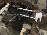
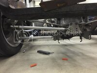
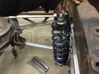
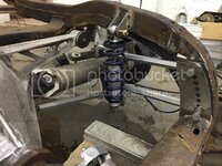
Looks like not much is different, but this side of the suspension is almost fully functional! (still need to finish the toe rod) C4 shafts shortened with new spicer joints, shock mounts tacked in, and the frame rail is ready to start piecing back together!

37E8B018-1E14-456B-B964-E3054FDB9CEB_zpsfoaoylbf.jpg

2C536442-6E3F-4A4B-84BD-B93261F459D1_zpsydwrhihb.jpg


Not going to mount the toe rods coincident with the half shafts like Stroker 427s design?

Im ditching the bracket so I can raise the inner pivot up like you said. My plan now is to use the two lower M10 bolts (the ones that bolted my previous bracket to the batwing) and cut the spring perch off so I can use them as my pivot point. They are grade 10.9 so from what Im reading they should have sufficient shear strength to handle the tie rods. I think drilling the rear cover out to fit a .5" bolt would weaken the boss that they thread into too much.
 
Looks good, the C4 rear swap is probably the most cost effective rear upgrade for a C3. How much did you remove from the 1/2 shafts?
 
Back
Top