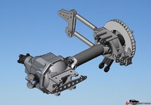
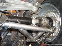
Six Link Rear Suspension

VetteMod - Corvette Restoration, Modding & Performance Forum

Help Support VetteMod Forum:

That was a big problem..... I was looking for this kind of pipe for few weeks, but with no chances!

Finally I decided to cut a rectangle of SS of 3mm and a friend of mine rolled in a pipe.
Then some good welding and the job was done!!!
 
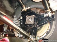
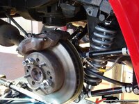
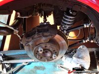
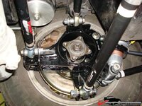
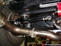
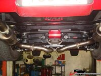
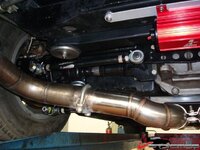
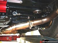
The last design (the one I have istalled in my car) was in 3mm Stainless Steel.
3 layers where the bearing support is bolted, 2 layers where the two front rods (and the shock) are bolted and only one layer where the toe-rod and the leaf spring are connected.
It is pretty light..... and pretty stiff.

Somewhere there are the pics of this release.... but right now I'm not able to recover the data from my old hard drive..... f...k !

So, you basically had 3 sandwiched sheets on one side, the other was 2 sandwiched ones? That would be cheaper and lighter than cutting thick stainless or steel plates. Usually with anything over 5mm a laser has to make 2 passes.
 
With the today's power of Lasers you can cut even 15mm of stainless in one pass (as you know I produce Laser systems)..... but I chosed this configuration basically for one reason..... the possibility to place meat where I really need it !

A lot of spot welding.... some trouble for the assembly.... but the result was pretty good!

1449b5a3d55644e.jpg
 
Yours is different indeed, there are a couple more holes & slots and the forward links don't have the upper mounting hole, just the lower one.

I'm assembling the model and if you reduce the plate thickness and stack layers then you need to modify all the other brackets too because they are notched/cut for 6mm plates.
 
I assume you are right...... because I'm in the impossibility to verify my drawings..... unless I will try to read my hard disk with a lens!!!!!!!!!!!!!!
 
Last edited:
Some other irregularities, the pickuup points for the sway bar seem to be lower on Yves' part than on my model.

Also, I'm not sure where to place the attachment ears for the toe control rod, they look different than the ones in Yves' pics. Also, what is the other part?

249b5b33ae1547.jpg

With this model, I hope I can easily change the parts to suit other applications (no leaf spring, thinner gauge plates stacked like you did) and possibly provide an easy to follow blow up pic/assembly manual.

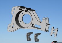
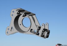
This is with the toe brackets, but they don't seem to fit very well:

249b5b73c67e58.jpg

I'll make these assemblies separate for the hub carriers, the center toe control bracket and the trailing arm pocket brackets.

From the differences, I assume Yves has a later revision than I have here.
 
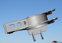
This shows the stacked plates idea: (I did these, they are not in the zip file like this)

249b5b3bb9d3d8.jpg

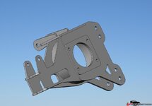
And here is one of the problems, look at the imrpoper fit on the left:

249b5b3bab3379.jpg
 
Marck, may you can try to get the drawings from Yves.... I'm very very sorry.... but my old PC is totally dead.

Of course the drawings for the stacked version are a bit different.

The only thing I have is the two DWG files I sent to Yves.... the second because I forgot to put a couple of items in the first drawing.

Can I attach a DWG file?
 
No need to apologize, we should all be thanking you on our knees for giving up this design for free. :1st:

You should be able to attach a 20K max DXF now. Let me know if it needs to be larger.
 
TT, I think that the ears for the toe rod need to point down, however I'm completly sure. Anyway that is how I welded it.

I just used a round tube of 165 mm that I had turned for the firs 1,5 cm to the right diameter, works like a charm.

Paolo, i will send you the files.

Marck, if you need them, just pm me your email and i'll send them right over.
 
Last edited:
Please send them twinturbo @ home.nl

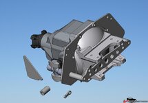
I think I'm missing the brackets for the toe control setup. Also, I still don't know what that piece is in the 1st pic, on the bottom right.

I got this far, I'm stuck LOL

249b7d36b54957.jpg
 
TT, please note that you may need to massage the trailing arm a bit in the spot where the bearing housings arm goes under it. Mine didn't quit seat completely, so I will have to grind some off.
Furthermore, the brakebracket makes the bolts get so close to the assembly that it gets difficult to turn the bolt. Some grinding there also.
 
I don't think I will be building this anytime soon, maybe in the future for Xanders car. I still have too much work to do with this:

2480f09ee9559d.jpg
 
I just got the files that Yves has, they ARE different and contain some more parts and don't contain 2 parts that I still don't know what they are (the unidentified ones in my 1st pic)

Here's how far I got with the toe control stuff, the upper camber struts are still missing. What goes where?

249b8443428361.jpg

A NOTE TO EVERYONE WHO DOWNLOADED THE FILES!!!!

They are NOT the latest revision and they are not complete, it's missing parts of the toe control setup. Will replace the file with the correct one, I will post here when done.
 
TT the triangles are for welding the whole assembly up in a square position.

The rod shape things are for the plates that mount on the diff and make up for the height difference.

The round tubes with threads are for the upper control arms.
 
The triangle is just a jigging tool?

Where do those con rod shaped things go then? against the diff lid?

Looks like I'm still missing pieces for the upper rods and the gussets for the lower standoff tubes right?
 
The smaller end of the rod type thingies are welded to the plate with the smaller end. If you have a spare diff you can test fit it, you will see that there is a height difference that makes the plate sit wrong. I thought that Paolo had a good drawing of them.

The pieces for those upper rods are the round ones with the inner thread. The have a thread on both sides, so you can run a bolt through the plate and into the tube. I'm going to weld some additional reinforcements on them. For the rest the upper rods connect to the top plate with the two things sticking out of them. hmm difficult to discribe it.

What do you mean with the standoff tubes ?
I will try to mock something up tomorrow and take pictures. Maybe it will clear it up.
 
I know the diff lid has a thicker boss aroudn the upper 2 bolts, is that what you mean?

If so, the little rod thing goes under one of the other 2 bolts??? What about the other one, is it not shimmed?

I'm looking forward to the pics LOL
 
TT, haven't had the time this weekend, but I found some pictures that Paolo sent me. They will be as helpfull...

suspension1.jpg
 
Ah, okay....yes the upper 2 bosses on the lid are thicker, like I said. So they go udner the 2 other bolts, but what's the other little end for? Something threaded in there In my model they are nowhere near large enough to span from a bolt hole to one of those standoffs (the tubes for the rods) Also, the triangular gussets on the tubes are not in the cutting template, at least not in mine.

So your guy cut the entire shebang for 160 euros? That's damned cheap, I'll have to se if I can get it done for that amount, I fear it will be more expensive.
 
The small end is for spot welding it to the plate.

The triangular pieces for reinforcing are indeed not in the drawings. You'll have to make them up.
 
Back
Top