Rookie's First Restoration Attempt...

VetteMod - Corvette Restoration, Modding & Performance Forum

Help Support VetteMod Forum:

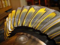
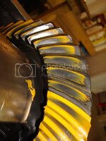
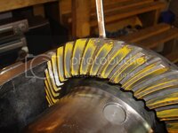
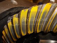
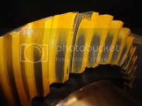
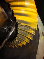
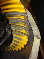
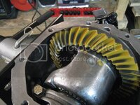
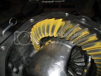
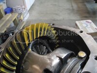
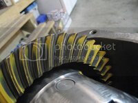
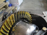
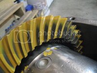
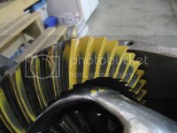
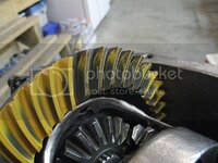
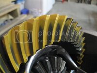
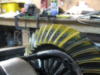
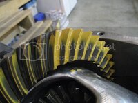
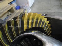
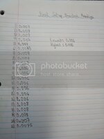
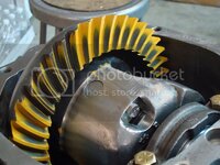
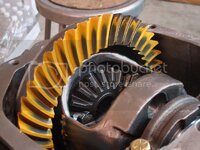
Okay Gary, I did a few things tonight. First I took my final good bearing and used it for the setup - my old one was giving me false readings with the torque wrench (which, by the way, is a great tool to add to my collection). I polished the black coating off the top of the pinion with very fine sandpaper. As expected, the new bearing gave very consistent reading with the torque wrench. I will need to get a new timken bearing from my bearing supplier on Monday. I increased the shim thickness even more so the carrier was a very snug fit in the housing - I can pull it out with my hands, but I have to work it out of the housing...it takes some effort). Anyways, here's the pattern with a 0.028 shim - I think I need to get a 0.027 shim ground to size, as my shims only come in 2 thou increments. I think I am close with the pattern now. I can see the end of the road with this diff rebuild:D

Pinion Shim: 0.028
Pinion Drag: 15-17 in/lbs
Left Shim: 0.038
Right Shim: 0.041
Backlash: 0.0065,0.007,0.008,0.0065,0.008,0.0065

DSC02930.jpg

DSC02931.jpg

DSC02932.jpg

DSC02933.jpg

DSC02934.jpg
 
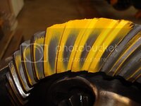
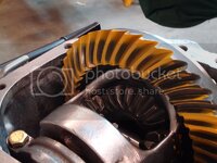
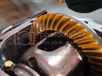
Tried the 0.026 shim again as I didn't have it a snug fit the last time I did it. What do you think?

Pinion Shim :
0.026
Drag: 17-18 in/lbs
Left Shims: 0.041
Right Shims: 0.038
Backlash: 0.005-0.008

DSC02936.jpg

DSC02938.jpg

DSC02939.jpg

DSC02940.jpg

DSC02942.jpg
 
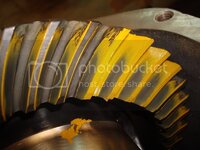
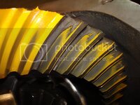
Installed the two new pinion bearings (the final good ones) and set the drag to 18-19 in/lbs. Did another pattern (still haven't installed the preload shims), and the fu*ker went deep in one area (couple of teeth). The backlash is lowest 0.006 and highest 0.0085. I'm not sure of what to do now - the majority of the teeth look good...so this may be the best I'll be able to get it. I'll wait too hear back from GTR1999 and tracdogg.

IMG_2288.jpg

IMG_2287.jpg

IMG_2286.jpg

IMG_2285.jpg

IMG_2284.jpg

IMG_2283.jpg

IMG_2282.jpg

IMG_2281.jpg

IMG_2280.jpg

IMG_2279.jpg

IMG_2278.jpg

IMG_2277.jpg
 
Jeremy,
This ofren happens when switching from the setup bearing to the final assembly. Gary and I go thru this on nearly every diff we do. Your pattern has gone deep in the root and moved to the toe. Here's your choices:
Open the backlash more not a good idea
Pull it back apart, change to a .024 or .025 shim. You might have to buy another bearing. best way
Run it as is. it will wear in but it will probably howl a little at light throttle when hot.
The biggest problem with the pattern is the pinion is touching the toe edge of the ring gear.
I highly recommemed you pull it back apart and install the .024 shim. Then adjust you final pattern with the backlash.
Mike


Most of the teeth seem to be good, the only ones which concern me are these ones...
IMG_2280.jpg

I have another brand new inner pinion bearing at home - I bought an extra one the other day in case something like this happened (which was a good idea). I only have a 0.024 shim. I don't care how long this takes me, I want to do it right...I've put too much time into this thing to have it howl just a little under low throttle. SHould I press off the bearing and install the 0.024 shim, or should I get a 0.025 shim ground to size?

Jeremy,
This ofren happens when switching from the setup bearing to the final assembly. Gary and I go thru this on nearly every diff we do. Your pattern has gone deep in the root and moved to the toe. Here's your choices:
Open the backlash more not a good idea
Pull it back apart, change to a .024 or .025 shim. You might have to buy another bearing. best way
Run it as is. it will wear in but it will probably howl a little at light throttle when hot.
The biggest problem with the pattern is the pinion is touching the toe edge of the ring gear.
I highly recommemed you pull it back apart and install the .024 shim. Then adjust you final pattern with the backlash.
Mike


Most of the teeth seem to be good, the only ones which concern me are these ones...
IMG_2280.jpg

I have another brand new inner pinion bearing at home - I bought an extra one the other day in case something like this happened (which was a good idea). I only have a 0.024 shim. I don't care how long this takes me, I want to do it right...I've put too much time into this thing to have it howl just a little under low throttle. SHould I press off the bearing and install the 0.024 shim, or should I get a 0.025 shim ground to size?
 
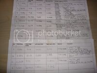
This is what it has taken me to get to this point of the diff rebuild...

DSC02968.jpg

Not to mention how many damn cans of brake cleaner I have gone through:lol:
 
This is the last pattern I think - Gary and Mike just need to give me the okay, but everything is installed now and all I have left to do are the minor details (still have to fit side yokes, install socket cap screws, clean off the marking compound...)

pinion drag - 16-18.5
backlash - 0.006-0.008
DSC02972.jpg


DSC02997.jpg

DSC02991.jpg

DSC02988.jpg

DSC02984.jpg
 
As an Amazon Associate we earn from qualifying purchases. Product prices and availability are accurate as of the date/time indicated and are subject to change.
Need to get myself a fill plug and two bottles of GM additive, but other than that, she is done.

DSC03028.jpg

Its been sitting like this since 12:00 last night, and no oil was leaking since I checked it last (a few hours after 12:00). Now I can start reinstalling the rear suspension!
 
I haven't been able to update this thread in a while due to me being occupied with my diff paper, sleeping, working, working on the vette...you know...the usual. Anyways, here's what I have been working on the past few days.

I stripped my trailing arm bolts from Vansteel - made of chinese crap I assume, because I was using a brand new torque wrench, recently calibrated and everything. Anyways, I decided I wasn't happy with the bolt quality, so I took a different approach. I went out to my industrial fastener place, and picked myself up some 7/16''-20 6'' grade 8 bolts (the vendors are supplying grade 5). The reason I bought them so long was because when you use a die to extend threads on a bolt, the few threads after the ones the factory rolled on don't have lots of bite to them. I wanted to basically have a shank with a hex head from which I could work off of. Now, I realize that cut threads are not as strong as rolled threads, but I am using grade 8, instead of grade 5, which will compensate from the "weaker" threads. I used a hand-drill to drill the cotter pin holes. You only want to cut enough threads in the bolt so that the nut can clamp the trailing arm pocket...you don't want any threads inside the pocket, it is a pivot point and it will bite into the frame if you extend the threads too much. It takes some time, and I messed up a few bolts, but it works perfect now. Instead of torqueing them to 50 ft'lbs and risking stripping my new (better than any vendor) bolts, I did the following. I packed the shims in the trailing arms so that they were tight (hand to use a hammer to tap them in). Then I used two hand wrenches to tighten the nut as much as I could and until the cotter pin holes lined up with the slots. I used one old original castle nut, and a castle nut from my new tie rods (I'm upgrading to moog). This bolt is a pivot point, so as long as it is tight, you should be okay. Anti-seized the hell out of everything - there is no way this bolt is ever going to get stuck again now:devil:

DSC03078.jpg

DSC03077.jpg

DSC03076.jpg

I then installed the crossmember on the differential. I talked to Mike (tracdogg2) yesterday on the phone about this, and he said its the easiest way to install it, so I followed his orders. After I mounted the crossmember, he told me to put RTV in the cushions so it creates a tight seal that moisture can't get into - I used some Loctite RTV sealant that my dad bought me, it works great...

DSC03034.jpg

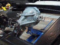
Installed the differential all by myself (at 8:00 am...no one was around to help:eek:), I used my foot to pump the jack and supported the diff with my hands (never again I may add):laughing:

DSC03037.jpg

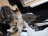
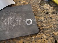
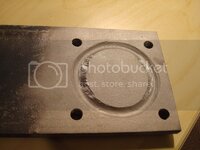
I cleaned out the sombrero holes beforehand using some q-tips and brake cleaner. A little bit of loctite on the bolts and then installed the aluminum disks my friend (he owns a machineshop) made me. It really stiffens up the crossmember.

DSC03083.jpg

I couldn't figure for the life of me how the front differential bushing was supposed to be installed, so I gave Mike another call and he walked me through it. He told me to use my original thick washer that I took off the car, the wimpy one they sell in the kits it pathetic. I couldn't find the original one, so I sandblasted one of my old spring washers, then welded the hole shut (it was too big), and then drilled the center out for a 7/16'' bolt. I hate cheap parts, I really do...

DSC03094.jpg

DSC03039.jpg

DSC03093.jpg

I'll update more when I have some more time, and when I fix my half-shafts (I have to redo them). The diff paper is coming along great, and I plan on adding more to it sometime this weekend. I think its already 10 pages:surprised
 
Forgot to post this before. I think I stripped and then threw away my original fill plug from my old cover at the beginning of the rebuild (can't remember if I threw it out). Anyways, being in Canada and everything, I wasn't going to wait two weeks for a new fill plug to arrive. I also wasn't going to pay $9 for a damn plug, and then pay another $7 for a red posi tag (hell, I'll be the only one doing service on this vette, so no need for the red tag anyways). So, I went to home Depot and bought myself a 3/4 pipe plug. I brought it home, and used my bench grinder to slowly grind the 3/4'' mark which was on the head of the plug. Then I used my wire wheel to make it nice and shiny. I only paid $0.93, and it looks and works great!

DSC03097.jpg
 
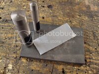
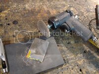
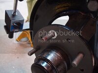
Finished the rotor runout on all four wheels using some aluminum from a pop can. If the material was too thick, then I used a surface prep tool to thin the "shim stock" down. I punches I used were 7/16'' and 3/4''. ). 0.003'' runout on the two front rotors. The rear rotors didn't even need shimming - they came in at 0.002 and 0.0025. Next time I'll be installing bolts like Gary does so the runout doesn't change - I'll have to buy some rotors with holes in them though. I have a nack for ruining new parts, and didn't want to mess anything up, so I left them just the way they were. Lots of people on here are running rotors just with lug nuts, so I'm not too worried.

DSC03101.jpg

DSC03105.jpg

DSC03103.jpg

DSC03104.jpg

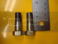
I also made myself the caliper mountign bolts. I originally uised a die to rethread a long bolt, but then I talked to Mike about it. He suggested not to use the bolt with cut threads, and to only do that in emergencies. The new one is on the right, and the old one is on the left.

DSC03107.jpg
 
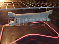
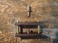
Made myself a tool yesterday so I don't mess up this u-joint install...

DSC03112.jpg

DSC03111.jpg
 
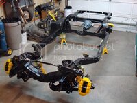
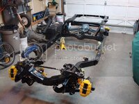
Change of plans for the engine, AGAIN:smack My dad doesn't want me pissing away all my money right now on a big block, and it isn't realistic for me. He want's me to rebuild my stock motor to 400 hp, 400 ft/lbs of torque. In 5 or 6 years when I have the money, then I can build myself a big block. ANyways, here's a pic I had of what the chassis looks like now. Still waiting on parts:cheers:

DSC03129.jpg
 
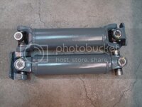
Rebuilt some new used half-shafts the past two days. I wasn't happy with my first attempt at installing the u-joints, so I picked up some used shafts at western corvette on Friday. I must have bent my original ones, because I couldn't for the life of me get the spicer u-joints from not binding. Anyways, here's how I did it this time.

DSC03135.jpg

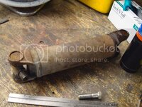
Instead of pressing out the joint and bending the yoke ears, i followed Gary's recommendation. I cut the old joints out using my angle grinder.

DSC03136.jpg

Then I used my propane torch to heat up the outside of the ears. I pooled some PB-blaster in the ears. The point of the heating was to accelerate the PB-blaster into working faster (yes, this trick does work, I've done it numerous times).

DSC03133.jpg

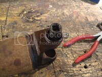
After letting the PB-blaster work its magic for a few minutes, I hammered out the caps using a socket and a fairly large hammer...

DSC03138.jpg

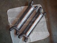
I sandblasted them, wire wheeled, then thoroughly degreased.

DSC03142.jpg

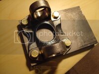
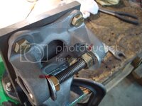
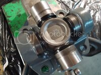
One of the half-shafts I bought came with the extra u-joint flange that I needed. I first cut out the old joints, but I couldn't get the caps out of the bores. I tried absolutely everything. I ended up resorting to my hydraulic press. I used my tool as a backing plate so the flange wouldn't bend. The bottom was still flat after I unbolted it, but the ears were now bent inwards :eek:. Then I gave Mike Dyer another call, and he suggested that I try bending it back. I mounted it on my backing plate, then spread the ears apart using this easy to make tool...

DSC03147.jpg

It worked great, way better than expected. The backing plate kept the flange base flat, while the ears were being spread back apart to their original shape. I powder coated the parts and installed the u-joints.

DSC03148.jpg

DSC03149.jpg

DSC03151-1.jpg
 
One other thing I forgot to mention. If your u-joint is quite tight, try tapping the half-shaft ears with a small hammer. It will seat the bearings, and it will feel different than before - much smoother.
 
e162f006.gif


Glad you took the time to re-post all this over here........ :thumbs:
I am going to put my son to reading this thread.

Keep it up.........your doing an excellent job. :drink:
 
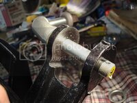
I'm having real big problems with my offset trailing arms right now - they don't fit, even though my frame pockets are perfect. I'll have to clearance the c-channel a bit on them for extra insurance when I get an alignment done...I don't want these things rubbing the top of the frame pockets. Anyways, here's another project I took on last night. When I was originally reassembling my trailing arms, I didn't think this bearign support ear was going to be an issue. It looks like the strut bushing shell dug into the ear over the past 30 years. I called Mike Dyer and asked him whether it is an issue, and he said I should fix it. I welded the groove in with my mig welder, then I ground it smooth and flush with the rest of the ear. I had the dumbest idea that the current running through the bearing support would seize up the bearings (yeah, I know, I'm an idiot for thinking that). He said to place the MIG ground on the other ear of the support, and just tack it around slowly. Worked great.

DSC03169.jpg

DSC03170.jpg

DSC03171.jpg
 
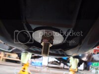
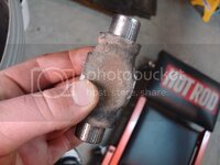
Homemade bushing installation tool - it cost me absolutely nothing. I did buy myself a small bench drill press for this project though to add to the collection:) The flaring tool is made out of an air chisel shank, and the bolt in the center aligns and holds the bushing in place while you flare it. I am going to cut 2 pieces of pipe to put on the long bolts so I know when to stop compressing the rubber. According to Mike dyer, it should be 2.25''.

DSC03235.jpg
 
again and again: great job :bounce::bounce::bounce:

Keep posting all these detailed and very helpful threads - thanks for taking the time to re-post all that info here.

Isnt' that bearing support cast ?? What rod did you use to weld it ? Inco ???
 
again and again: great job :bounce::bounce::bounce:

Keep posting all these detailed and very helpful threads - thanks for taking the time to re-post all that info here.

Isnt' that bearing support cast ?? What rod did you use to weld it ? Inco ???

Yes the bearing support is cast iron. I thought it was going to be a bitch to weld due to it being cast iron, but I thought I'd give it a shot after I talked to Mike dyer. He said to slowly work my way around the hole to reduce the amount of heat created and so I could see what I was doing. I used my mig welder, which has a mix of argon/co2 and solid core .030 wire. I also was afraid that the bearings were going to seize up on me, so I kept the ground clamp on the other bearing support ear which is really close to the area I was welding. Worked great.
 
It is most likely cast steel, not cast iron.... cast iron is pretty much unweldable

You're probably right, which is why it welded so nicely. I doubt i would have been able to weld it if it were cast iron.
 
what did you weld it with ? regular carbon steel ER70 ?? That's the stuff you buy at the hardware store, higher strength ER90 is not very common, you'll have to get that at a real welding supply store.... Inconell (inco82) is perfect for this, you can pretty much weld anything to anything with inco.... it does however require heat treatment (very slow cooldown) otherwise it's too hard/brittle....
 
what did you weld it with ? regular carbon steel ER70 ?? That's the stuff you buy at the hardware store, higher strength ER90 is not very common, you'll have to get that at a real welding supply store.... Inconell (inco82) is perfect for this, you can pretty much weld anything to anything with inco.... it does however require heat treatment (very slow cooldown) otherwise it's too hard/brittle....

I'm not sure? My uncle, who welds for a living, set me up with my millermatic 175 - its the catz ass for home use. I bought some stuff at a local welding supply house...all I know is that it is solid core 0.030 mig wire. I'll look closer at the spool later on tonight and see what the label says.
 
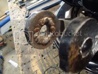
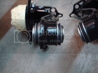
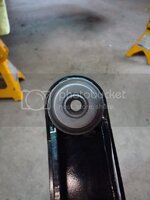
I found some issues with my offset trailing arms. For some reason, the bushing cups were being pushed out of the tube at the end of the arms. So I pulled them out and decided to remove the bushings out to see what was going on. After I pulled the bushings out, I found some issues with the way they were installed. There was an 1/8'' gap where the cups meet up in the middle. The cups were also not pressed into the piece of pipe on the end of the arm. I decided I wouldn't reinstall poly bushings because they aren't good for this application. This being said, it would require a lot of work to install them correctly.

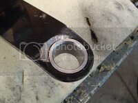
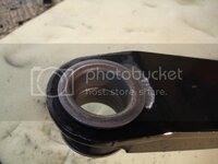
The first thing I did was remove the powdercoating from the ID of the pipe. I ground down the high spots which were preventing the previous bushing cups from sitting flat on the arm - this was very important, as they would be cocked if you tried to press them in.

Before:

DSC03240.jpg

DSC03245.jpg

After:

DSC03275.jpg

DSC03248.jpg

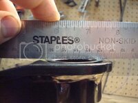
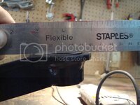
I used my dial caliper to measure how much I had to file the pipe down so that the bushing cups would meet in the middle once they were pressed in. The pipe also wasn't parallel for some reason. The important thing here was to make sure I made the pipe parallel as I filed away metal - this took a lot of time, patience and measuring. I eventually got it to where I wanted it. The next thing I needed to do was open up the bore so that the rubber bushing cups would be a press fit, but they wouldn't be so tight that the rubber wouldn't fit inside them anymore. The hole ID was too tight a press fit for the rubber bushing cups - they wouldn't have seated properly if I just installed them without opening up the bore first. I used my dremel tool and got it the best I could get it. I then pressed the cups into the arm, and the fit was perfect. The cups were really tight in the arm, and they met in the center as opposed to the previous 1/8'' gap I had with the poly bushings.

DSC03255.jpg

I then used my homemade tool to compress and flare my rubber bushings. I used my press to flare the end of the tube.

DSC03288.jpg

DSC03297-1.jpg

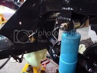
I also decided to install rubber bushings in my strut rods instead of the original poly ones. Rubber is much better for this application. I had to open up the bore on my strut rod ends so that the rubber bushing would be a press fit, but they wouldn't be so tight that the rubber would be oozing out of the ends of the bushings. Again, this took a lot of time, patience and measuring, but I got it done. After I finished this project, I had to clearance my offset arms so they wouldn't hit the pocket or shims. My pockets were in perfect condition, so I don't know why these arm's didn't fit. Basically, I havd to install absolutely everything on the rear end, and do a quick alignment for 1/4'' toe in (which is the worst case scenario for alignment specs), and then check the travel on the arm to see whether or not I needed to clearance them. Sure enough, they hit the pocket, and I had to pull everything apart, clearance the arms, reinstall, and check again. I got very frustrated with the fit of these arms considering that my pockets were in perfect condition. The rear end is almost complete - I just need to get one bolt for the upper shock mount and do one last alignment before I call it good. I bought the correct bolts for the half shaft flanges (the ones with the correct shank on them). I installed them, and twisted two of the french locks. I said screw it, and used loctite with locwashers instead. But when I tried to torque the bolts, the lockwashers kept splitting. I tried everything, then decided to try some brand new bolts to see if the face underneath the heads of my new correct bolts had been galled. Sure enough, my new bolts were the issue. So, I decided to make myself some new ones. I got some 1 3/4'' bolts, which have the smallest shank on them (which was a tiny bit too big, like 1 thread). I cut 1-2 threads extra on the shank just to make sure that it didn't bottom out on the flange when I tightened the bolts. It worked out perfectly. I used red loctite on the thread just to be safe and reinstalled everything successfully. You may have noticed that I didn't install my safety loops. THe reason being is because they get in the way of EVERYTHING. I'll use them on my next vette:lol:

DSC03307.jpg\

DSC03315.jpg

DSC03316.jpg

DSC03317.jpg

DSC03314.jpg
 
Okay, this has probably been the closest call with these offset arms - I did my rear end alignment today, and I was almost screwed for life...AND THIS IS DEFINITELY NOT DUE TO FRAME POCKET DAMAGE, MY FRAME POCKETS ARE IN PERFECT SHAPE. I aligned the entire rear end with the half shafts level. I dialed in each side for 0 camber and 0 toe in...I was almost on the brink of death with the right side - these arms obviously have some issues with them because they almost didn't fit for 0 toe-in. Maybe the arms were cocked when they were welded, who knows. Anyways, here is how I did it (Mike Dyer taught me this method over the phone...pure genius, thanks Mike:thumbs:). It is much more accurate than using a meter stick to do a rough alignment - this method is a thousand times more accurate, because it uses the entire frame rail to dial in the toe-in measurements...not just a tiny section of the frame rail.

The first thing I did was level off the frame. I used cardboard underneath the jack stands to make the frame perfectly level.


30mmwdf.jpg

mrzqyc.jpg

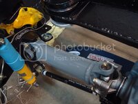
The smart struts are designed to limit camber throughout travel. This can be both a good and a bad thing. I'm not planning on taking this car to the track, just street driving, so limiting the camber would be the way to go in my application. To do this, you need to turn the camber bolts so that they are on the bottom of the slots - the smart strut bracket goes up and down, not left to right like the stock one does. I did the left side first, then I attempted to turn the camber bolts on the right side, and then snap:cuss:banghead:...

2vmd8v5.jpg

The son of a b8tch cracked in half, so the only choice I had left was to use one of my old camber bolts and washers. The original washers are different than the ones that came with my smart struts (they only had one flat on them) So I had to use an entire bolt assembly from my old struts.


2pqom6d.jpg

315dh0g.jpg

23wple0.jpg

2ceg3m1.jpg

Not the best option, but I'm not waiting on stupid parts anymore...nothing ever goes smooth with this stupid rebuild, I'm at my wits end with this project 1 step forward, then 30 steps back. Most of the time its because parts do not fit, and I then have to reengineer them to make them work. Okay now that I have vented, on with the alignment. After you torque the strut rod camber bolts, you are now ready to do the alignment. Take an old rotor and install it backwards on the lug studs...

14lkm5g.jpg

Raise the arm using a jack underneath the backwards rotor, so that the half shaft is perfectly level - use a small level for this. Once you get the half shaft level, dial in the camber so it is 0 (use a 2 foot level on the rotor pointing up to the roof) - get the bubble centered for zero camber.

Now, tie a piece of string to the area where the spring bolts go, wrap it around the back of the rotor, and then tie it to something heavy that you can move while dialing in the suspension - a jackstand would work well for this application, but I didn't have an extra one, so I just used a bicycle stand I found in the garage.


2cfxeu9.jpg

21qx3a.jpg

Now, here is the trick to this method. You want to move the stand you have the string tied to so that it just touches the fact of the rotor. Imagine you are trying to build a fence and this is your plumb line, or a massive ruler if you will. If you placed a meter stick on the face of the rotor, you can measur e the distance to the frame rails in two positions, but these positions would be relatively close together because the meter stick can only reach out so far. The string method allows you to measure an area at the front of the rail, and an area at the rear of the rail, you subtract these two numbers and end up with you spec. Make sure the section of frame rail you are working with is straight. If it isn't, you could always rig something up to the body mount cages to use as a straight line reference point. Contrary to what my pictures show, my frame is not perfect - in fact, the right frame rail had a huge dent in it which I removed and welded in new metal...but it still isn't perfect. So, I had to be careful when I did the toe-in on the right side of the frame, because it is a little "wonky" on the outboard side. Here you can see the two points I chose to measure from while doing the alignment - I used tape to mark them off. You only need two points.

2zp625u.jpg

Measurement at the front of the frame rail (after tweaking the trailing arm shims)

15md4xu.jpg

Measurement at the rear of the frame rail (after tweaking the trailing arm shims):

2mo3zfc.jpg

You want the measurements at both points to be the same - this means that you have zero toe-in and the rotor is perfectly in line with the chassis' frame. I don't trust alignment shops - I can do it myself and know exactly how well the job was done. Oh, and in regards to what my shims ended up looking like on both sides, here are two pics.

Left Side:

157opqf.jpg

Right Side:
2vjrhpf.jpg

Now you tell me - how lucky was I with the shims on the right side of the frame? I am going to do two more alignments just to make sure I'm safe on the right side, because if it turns out that my measurements were wrong, well then guess what? That means my aftermarket trailing arms were welded incorrectly and they are not straight. If I have to pull this trailing arm off the chassis again, I'm going to go into denial. I suggest you boys stick with the stock arms and avoid the hassle I have gone through with these arms - it just isn't worth it. If I would have known I was going to run into all these issues, I would have stuck with the stock arms...live and learn I guess.

 
With the halfshafts sitting level and setting toe to 0 you are always removing a bunch of shims from the outside because normally in that situation you would have some neg. toe because when the suspension moves away from horizontal, being it up or down it gains more toe out. If you set yours to 0 here you have toe out in every other position, which is a bad idea. Set the toe in, start off with around half a degree or so and adjust to your liking. In the end, your static ride height will most likely not be with level halfshafts so you will have to adjust for that. You really do not want to bump the suspension and go to toe out, it will create massive rear oversteer.

With a stock susp. height (that which the components are designed for) the halfshafts are aiming down, this means that for 0 toe you will have more outboard shims.

If you want to run a slammed ride and not worry about this you have to move the differential up to get the suspension to work around level shafts with a neg. toe setting.
 
With the halfshafts sitting level and setting toe to 0 you are always removing a bunch of shims from the outside because normally in that situation you would have some neg. toe because when the suspension moves away from horizontal, being it up or down it gains more toe out. If you set yours to 0 here you have toe out in every other position, which is a bad idea. Set the toe in, start off with around half a degree or so and adjust to your liking. In the end, your static ride height will most likely not be with level halfshafts so you will have to adjust for that. You really do not want to bump the suspension and go to toe out, it will create massive rear oversteer.

With a stock susp. height (that which the components are designed for) the halfshafts are aiming down, this means that for 0 toe you will have more outboard shims.

If you want to run a slammed ride and not worry about this you have to move the differential up to get the suspension to work around level shafts with a neg. toe setting.

I see what your saying. This is just for now...I will probably be adjusting it once I get weight and tires on the vette.
 
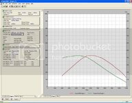
Been busy the past couple weeks - Mike has been helping me design my engine. I only had a magnum 270H cam for my desktop dyno, which is the closest I could find to the crane 272 cam which I will be using. I also only had AFR 190 heads - I'll be using AFR 180's, but it was the closest head file that I had for the program. Here is an overall pic of what I have come up with so far - I am still playing around with it.

2.jpg
 
Last edited:
You should have checked the downloads section, under engine & perf. there's a zip file with a bunch of dd2k head files, amongst them is.... sbc air flow research 180cc.flw
 
Back
Top