Plastic Fantastic 2

VetteMod - Corvette Restoration, Modding & Performance Forum

Help Support VetteMod Forum:

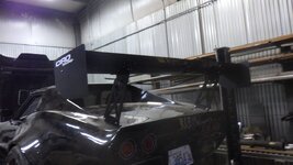
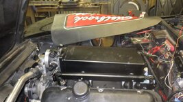
removed the last vestiges of Optima 2023.... put the wing back where it belongs
v86aUN1h.jpg
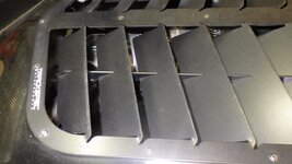
time to start considering what the front is going to look like - I don't think I'm getting enough air for cooling and adding more hp isn't going to help on that front (yes 511 ci is in sight)
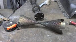
time to make the second baffle...
GhXiy5Jh.jpg
I'm going to fasten this differently - not sure how, yet, but it's important to get this all together
MoVwKeQh.jpg
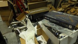
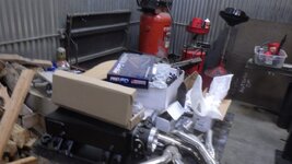
because I dug all this stuff out
u7YSew0h.jpg
e2OTXEah.jpg
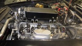
Paul's C3 - its motor is about ready to come out and several bits from my C3 are going on his motor...
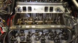
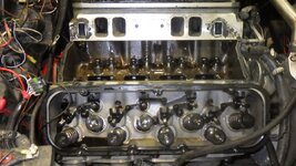
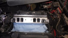
my plan is to get the hard parts on the motor - though I may get dead stopped because I'm not 100% sure I have an intake gasket
 
time to do this
GCYIsNlh.jpg
pictures to give a reference for putting all this stuff in Paul's car
KNwYPMwh.jpg
qEMTfl8h.jpg
M2Wyzeuh.jpg
I hope this fixes the oil pressure problem - it certainly looks like it might be too much lift... but there's another problem and that's they were just too tight in the bores. The Comp lifters are much smoother
1xtIQRfh.jpg
and I'm just going to pretend I didn't see the cam.... billet cam. It'll be fine. Or it won't. I'm not doing anything with it at the moment....
AjZNJp2h.jpg
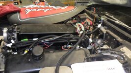
wow, even room under the hood
GthQY6sh.jpg
P7Mi42Bh.jpg
 
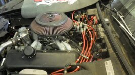
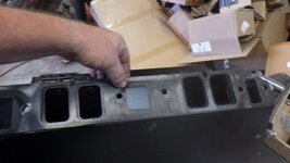
one thing for certain, small intake runners
1yhKjqGh.jpg
Rpq25Mlh.jpg
but whatever, time for glue
hLrhxYDh.jpg
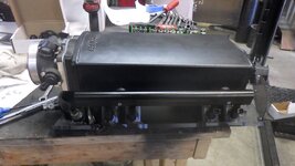
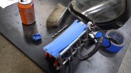
assemble intake
O3F4mqGh.jpg
do not like the path of the crossover...
XWgImSJh.jpg

time to order parts - I bought the wrong injector harness, can't find the coolant tube where the fill is in the hose.... nor do I have any idea where my intake coolant elbows are (but the few I have probably are wrong)... and I need a throttle cable... I have plenty to do while waiting
 
As an Amazon Associate we earn from qualifying purchases. Product prices and availability are accurate as of the date/time indicated and are subject to change.
One bite at a time... cooling
as much as I don't like chrome, it fits
v2wbWhMh.jpg
then fix the coolant bypass.... for whatever reason, the FiTech coolant hole is about 1" closer to the water pump
S2R6qZzh.jpg
rant ON
I paid money for a throttle cable adapter for this manifold. It simply doesn't work.... hell, I'm not even sure the pieces bolt together.... I've been apologetic about FiTech but this is quite literally it. Never use them.
mEXV0Xyh.jpg
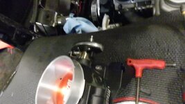
the bracket needs to be 5/8" wider to clear the throttle body.... now I either have to make or buy something else...
in an effort to calm down....I dropped the cam sensor in place - not the right place, but the place where the cat won't knock it off the bench...
ADSvyeQh.jpg

but that is progress.... but now I need another bracket, and the more I look at it, the more likely I'm going to re-engineer the cooling system. I'm tired of cooling problems...
 
the more I look at it, the more likely I'm going to re-engineer the cooling system. I'm tired of cooling problems...
Fans? Ducting? Hood exits? Bigger? Higher pressure system - like NASCAR? Do tell.
I've been in the "Skunk-Works" working front uprights, so can't share that.

Cheers - Jim
 
full.jpg
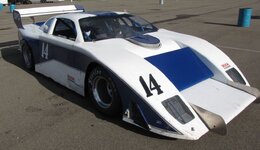
A few years back - Jeff placed this up for sale. Even though I wasn't in the market, he spent a good bit of time on the phone with me. Just to engineers rapping. He was very open about his approach to this car and was very satisfied with the results.
full.jpg

We never spoke specifically about "overheating" but talked about the flow aspects and were there any problems. I like the duct dumping out forward of the wheel housing.
I recall you "know a guy" that could build the radiators. Perhaps he could have some useful ideas how to keep both operating to keep the temps in range? This would be an interesting, radical, yet potentially useful approach.
full.jpg

It seems like there might be enough real estate there, but can't say for sure. Sample of a German C3:
1694195003480.png
Looks like they were shaping the air some too. Brakes I reckon, and the center to the radiator - transmission in the upper- or intercooler?

Otherwise, there are numerous approaches to the ducting. Look forward to watching between wrenching sessions!

Cheers - Jim
 
I got ghosted by the radiator manufacturer who was supposed to prototype a radiator where the tubes were not perpendicular to the tanks. I still think that wouldn't be a terrible way to go - but I need to get it running again first.... then I'll do something like the German C3's design... problem with the rubber bumper cars is the point is further forward from the wheel centerline.... not optimal
 
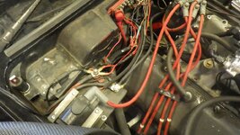
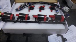
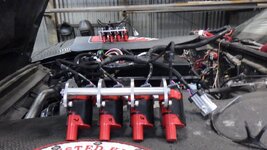
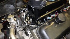
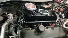
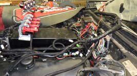
Time to figure out where to mount the coils. This isn't a terrible place except it looks like crap and would make adjusting the valves one step closer to hell
7wJIudgh.jpg
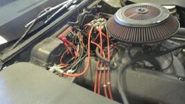
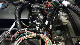
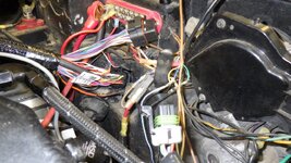
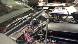
I started to run the wires under the intake then realized about 1/2 of it is unknow or unnecessary
RC65wvQh.jpg
time to make yet a larger hole in the firewall
YIrJtorh.jpg
better
nuY8n3Vh.jpg
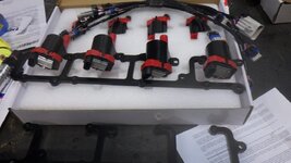
template for coils
5soqolbh.jpg
then realized I don't have fasteners that will work
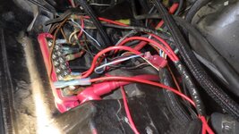
another view of the wires that go through the firewall
c0qTqAWh.jpg
a preview of where the fasteners must go....
CpIwwOzh.jpg
 
In today's installment on how to go bankrupt with a simple install, let's talk crank triggers. For this installment, we'll feature our spokes BS'er and overall bicyclist hater, Chad "the square exhaust" guru.
[VIDEO]
8 minutes I won't get back - and the ONE question I had.... no answer, accessories.... how do you install them? I should have figured, the universe hates me and Chad is the universe's spokesmodel.

that said, in all fairness, none of the 'solutions' talk about that issue... time to deep dive Yellowbullet I guess....
 
Are the rotors coated? - Or are they Carbon/Ceramic? The vanes make me think - maybe not - but do tell...

Accessories? AirCon/Radio? or support for the fuel system and maybe water pump (electric?) throttle, steering, dry sump, etc.
Crank trigger install is pretty easy - but then the rest of the system - that is a a few months out for me. I hope the Electrodyne is still functional!

May start milling the uprights for the front next week. Just about settled on a design that I'm happy with the numbers.

BTW - I run most YTs at 2x and then sort and revisit what makes sense. I would have burned "only" 4 minutes! ;)

Cheers - Jim
 
Are the rotors coated? - Or are they Carbon/Ceramic? The vanes make me think - maybe not - but do tell...

Accessories? AirCon/Radio? or support for the fuel system and maybe water pump (electric?) throttle, steering, dry sump, etc.
Crank trigger install is pretty easy - but then the rest of the system - that is a a few months out for me. I hope the Electrodyne is still functional!

May start milling the uprights for the front next week. Just about settled on a design that I'm happy with the numbers.

BTW - I run most YTs at 2x and then sort and revisit what makes sense. I would have burned "only" 4 minutes! ;)

Cheers - Jim
the rotors are steel, but remember, I'm running Camaro bits - thus these are for a SS Camaro
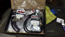
accessories - hydraulic pump, water, alternator. I'm still deciding on maybe running an electric pump - while it would hinder at WOT throttle on the track (mechanical pumps flow more) at the idle to 4000 rpm, it'd flow more..... I dunno, taking this one bite at a time. I ordered a FAST setup (cheaper by a little bit).

I hate wiring, but this is kind of fun puzzling through the challenges.
 
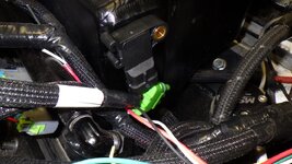
so Holley, please tell me why if I buy your overpriced part, it's got the wrong connector on it... this isn't a huge deal by any stretch but when you order the part specifically from the tech guy at Holley, one should expect it to work without modification.
lZMJD8Th.jpg
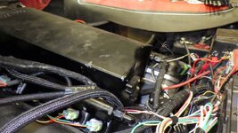
very expensive bag of wires
vS2kdRth.jpg
planned to work on the fuel system... got distracted but here's the before picture
hJKx3AHh.jpg

still waiting for parts, think I'll tuck the Blazer away for a minute while I finish this... problem is I get the next shipment on Thursday - and I need to almost immediately leave for Lake Tahoe to go wheeling over the weekend...
I'll sleep when I'm dead....
 
When I bought my EFI from Holley, I called the Tech line and asked which version of it I should buy. The "tech" guy told me to buy one that I knew was not correct and pressured me to buy it while I was on the phone.

I think by "tech" they mean "sales" department.
 
Pg 25 was first posts (working backwards) I saw on those diffuser ducts In
Internal Body Aerodynamics Thread. There should be a bunch of older posts.
 
Yeah, I think if you look at pg 25 it shows a splitter diffuser. #488 & #495.

I think there were a bunch of other posts, you would just have to work backwards to find them.

The same principle as a rear diffuser.
 
It is an effective approach. Implemented on the little sports racer. Did a few trials, but then sold the car.
So, sorry have no personal experience I can add - but will incorporate on Elvira too.
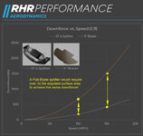
It represents up to an effective "doubling" (as I recall ) of the splitter area. Here is the chart I posted fro RHR a while back:

1696814476015.jpeg
GO FOR IT!

Cheers - Jim
 
It is an effective approach. Implemented on the little sports racer. Did a few trials, but then sold the car.
So, sorry have no personal experience I can add - but will incorporate on Elvira too.
It represents up to an effective "doubling" (as I recall ) of the splitter area. Here is the chart I posted fro RHR a while back:

View attachment 55892
GO FOR IT!

Cheers - Jim
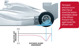
but where he loses me is the answer to this question - it creates a low pressure somewhere, where? If I'm looking at that correctly, the air hits the tire and tumbles out.... what am I not getting?

and the why I'm pursuing this... if it creates low pressure at those bumps (I know, it's early and my technical terms don't wake up until later) - could I duct that air into the radiator and get a similar result?
 
but where he loses me is the answer to this question - it creates a low pressure somewhere, where? If I'm looking at that correctly, the air hits the tire and tumbles out.... what am I not getting?

and the why I'm pursuing this... if it creates low pressure at those bumps (I know, it's early and my technical terms don't wake up until later) - could I duct that air into the radiator and get a similar result?
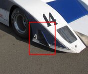
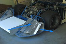
These front splitter "diffusers" do not make downforce at the discharge end, they actually create a low pressure area at the point where the floor of the diffuser starts to diverge from the ground. It works the same as diffusers at the rear of the car. If you create back pressure at the discharge end of the diffuser -- like air hitting the tire or ducting into a radiator, for example, you reduce the effectiveness of the diffuser. The angle of the "upslope" of the diffuser is also critical. If it is too steep (greater than 12-15*), then the airflow will go turbulent and you lose the low pressure area. The arrows in the second photo show where the greatest downforce is created. These things really work! Hope this helps.


Diffuser.jpgCable - Splitter 3-1.jpg
 
Well explained Pappy.
That is why the diffuser "mod" on the splitter "effectively" lengthens the spltter.
The lower pressure is moved forward and increases the downforce lever.
Cheers - Jim
 
Back
Top