
You are using an out of date browser. It may not display this or other websites correctly.
You should upgrade or use an alternative browser.
You should upgrade or use an alternative browser.
Internal Body Aerodynamics
- Thread starter vette427sbc
- Start date

Help Support VetteMod Forum:

69427
The Artist formerly known as Turbo84
- Joined
- Mar 30, 2008
- Messages
- 3,080
- Reaction score
- 42
- City & State/Province
- Clinging to my guns and religion in KCMO.
I'll second what Pappy said. And as I often do, add a few comments;
...................
He has the side skirts figured out, I believe. Sharp corners tend to not let air wrap around and get back underneath the car. Also if you are not concerned with sanctioning rules, or ride height restrictions, you could add PVC verticals reaching to almost ground level. They will make the car ride like on rails when matched with a full belly pan. I ran that on the SR (illegal in my class - then pulled to race) and the difference was night and day. Wish I had the data to prove it - we bought the data boxes later that season.
..............
ENOUGH! I hear you say.
I say, Cheers - Jim
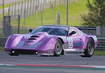
I've often wondered about the sharp edge shape there. I hope you're correct, as that's an easy piece/shape to fabricate. Years ago I replaced my short height rocker panels with longer (lower) pieces of Lexan (painted black), as I hated the side view with the transmission crossmember visible under the rockers. I like the looks of the rocker panels now, but I'm often scratching my head trying to figure out if I'm reducing external airflow from getting under the car, or if I'm trapping undercar air from getting out sideways. I've kicked around putting a scoop or two inboard of the rockers to scoop out undercar air and vent it out through some blacked out screens in the rocker panel. I'd like to do some actual differential pressure measurements in that area, but I haven't completely worked out how to get an accurate reading there given the moving/fast/turbulent air in those areas.
Just something for me to figure out over the winter.

Wheel discs like on that Porsche a few pages back would likely work on grand sport rims.
Looks like cutting out the quarter panels is popular, but making it looks look good would take some effort.
Rear view cameras instead of mirrors.
Splitters work.
I’m seeing C7 widebody kits with the back of the flare cut out. It might be cosmetic, but some of these high end cars show that. So, could do that on a C3.
69427 has body panels under his car.
Yes, canards might even look good.
I guess it depends on how far you want to go.
Here is an example of the c7 widebody with the fender flares cut out. There is a better vid, just can’t find it.
Am I going to do it ? Probably not, but I am interested in the topic.
"Rear view cameras instead of mirrors". Great idea. The mirrors on a C3 are pretty useless.
I did a search to see if these exist. Unfortunately Google confuses this with a rear view mirror and there looks to be 100's of option. I think I'm seeing that the manufacturers want to do this but there are DOT requirements to have physical mirrors on the doors.

rtj
Well-known member
- Joined
- Nov 5, 2011
- Messages
- 3,598
- Reaction score
- 211
Wheel discs like on that Porsche a few pages back would likely work on grand sport rims.
Looks like cutting out the quarter panels is popular, but making it looks look good would take some effort.
Rear view cameras instead of mirrors. [/B.
"Rear view cameras instead of mirrors". Great idea. The mirrors on a C3 are pretty useless.
I did a search to see if these exist. Unfortunately Google confuses this with a rear view mirror and there looks to be 100's of option. I think I'm seeing that the manufacturers want to do this but there are DOT requirements to have physical mirrors on the doors.
I have a bunch old iPhones and was planning to use one for a speedometer. I think the gps still works, maybe not. But, you could also make the side mirror displays with them and a couple of Bluetooth cameras. Yes, I’m cheap.

But, camera display kits are probably available for reasonable prices.
I was looking for these and realized I had posted them before (they were in myimages).
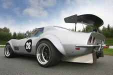
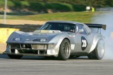
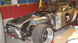
I’ve always admired this car. He made a thread on DC a long time ago. Maybe if I step up my engine game a lot....
Last edited:

phantomjock
Well-known member
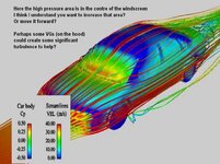
Yes the edge does keep the flow from "wrapping around". Here you can see the CFD streamlines over the fenders "wrap" (also pushed by the windscreen) - but note they are "tripped by the A-Pillar. You's want to keep the low pressure under the car from filling and losing the downforce you'd generate. Ignore the text on the slide - recycling a pic for the streamlines...I've often wondered about the sharp edge shape there. I hope you're correct, as that's an easy piece/shape to fabricate.
I'm doing that on my car and will extend the side "box" to the rear fenders, and blend it in with an upward sweep. I want to send the flow over the top of the rear wheels through the fenders. [need to start building those soon] An advantage to that design is you can use the box for side pipes (cleaning up underneath for a belly pan) or from an aero perspective make the interior volume into its own tunnel. Small but every bit helps. And, it is at the mid-point on the body so helps keep the aero-balance.
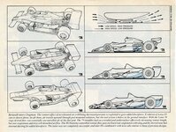
There is a lot going on in that picture of a formula car - but you'll get the idea of using the side "pod" to aero advantage. If a "box" like on the purple car - fill and shape the interior like a tunnel/diffuser. Or build it lower in front so it has a natural rake. Remember to add the side skirts inside and out. Again, easy to build and replace -- like your rockers. Easy to test with a few pressure taps too.
Yes - and Yes. Keeping the outside air from flowing in - and reducing the low pressure you're created (with the side skirts and chassis rake). Also, keeping the underneath flow in as long as possible to get the low pressure region back to the rear of the car to exit (hopefully) through a diffuser. As an example of the effort - you've seen semi-trailers with the side skirts. They hit up to 25% reduction in drag when used with the boat-tail plastic panels.Years ago I replaced my short height rocker panels with longer (lower) pieces of Lexan (painted black), as I hated the side view with the transmission cross-member visible under the rockers. I like the looks of the rocker panels now, but I'm often scratching my head trying to figure out if I'm reducing external airflow from getting under the car, or if I'm trapping undercar air from getting out sideways.
With some vanes to direct flow from aft of the wheel well into that region could be useful. The flow could then exit through the screens. Not likely to get much flow that is further aft under the body to move forward to those. It might reduce the overall low pressure region created though.I've kicked around putting a scoop or two inboard of the rockers to scoop out undercar air and vent it out through some blacked out screens in the rocker panel. I'd like to do some actual differential pressure measurements in that area, but I haven't completely worked out how to get an accurate reading there given the moving/fast/turbulent air in those areas.
Testing would be a very good idea! Would really like to see some numbers before/after. Quite a simple setup I'd think too. Use 2 sets of rockers (with/without screens). I wouldn't try one each side - afraid the data would be corrupted. Here is an idea like I understand you are suggesting:
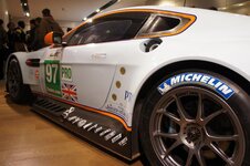
He has the side pipes in the forward area and the louvers for cooling(?). Note the exit of the exhaust mid-length.
Cheers - Jim
BTW - I'm putting together a compendium of C3 ideas for aero - I hope it makes some sense. This Thread and others bring out a lot of good examples to pick from.

Last edited:


![Pampers Sensitive Baby Wipes, Clinically Proven, Fragrance Free, Unscented, Water Based, Hypoallergenic, Multi-Use, Hand Wipes 336 Wipes Total (6X Flip-Top Packs) [Packaging May Vary]](https://m.media-amazon.com/images/I/41KLBHu9CAL._SL500_.jpg)





As an Amazon Associate we earn from qualifying purchases. Product prices and availability are accurate as of the date/time indicated and are subject to change.

mfain
Well-known member
^^^^^^^
While I like the looks of the "bowl", I suspect that the aerodynamics would be better if it was covered with a flat disk.
While I like the looks of the "bowl", I suspect that the aerodynamics would be better if it was covered with a flat disk.
phantomjock
Well-known member
A lot of effort that hearkens back to post #317!
Interesting paddle-wheel effect to get the air out, as opposed to making it more like a "screw" aligned web.
Cheers - Jim
Interesting paddle-wheel effect to get the air out, as opposed to making it more like a "screw" aligned web.
Cheers - Jim
I'm not understanding how the straight vanes "pump" air through the wheel?
rtj
Well-known member
- Joined
- Nov 5, 2011
- Messages
- 3,598
- Reaction score
- 211
I believe they are basically centrifugal compressors. Early and/or cheap centrifugal compressors had/have straight vanes.
https://en.m.wikipedia.org/wiki/Centrifugal_compressor
I am guessing he found a stainless salad bowl approximately the right size and went from there.
We had a thread on the original alloy fans, I seem to remember they were flat on the front, but alloy would support a lot more torque. It was just uploaded, so it will be interesting if he gives an update later.
Found it:
http://www.vettemod.com/forum/showthread.php?t=10716&highlight=Wheel+fans
https://en.m.wikipedia.org/wiki/Centrifugal_compressor
I am guessing he found a stainless salad bowl approximately the right size and went from there.
We had a thread on the original alloy fans, I seem to remember they were flat on the front, but alloy would support a lot more torque. It was just uploaded, so it will be interesting if he gives an update later.
Found it:
http://www.vettemod.com/forum/showthread.php?t=10716&highlight=Wheel+fans
Last edited:
I believe they are basically centrifugal compressors. Early and/or cheap centrifugal compressors had/have straight vanes.
https://en.m.wikipedia.org/wiki/Centrifugal_compressor
I am guessing he found a stainless salad bowl approximately the right size and went from there.
We had a thread on the original alloy fans, I seem to remember they were flat on the front, but alloy would support a lot more torque. It was just uploaded, so it will be interesting if he gives an update later.
Found it:
http://www.vettemod.com/forum/showthread.php?t=10716&highlight=Wheel+fans
I still don't think that does anything other than churn air. Its not even centrifugal, and if it was, its backwards. This is from the link you provided:
Impellers are designed in many configurations including "open" (visible blades), "covered or shrouded", "with splitters" (every other inducer removed) and "w/o splitters" (all full blades). Both Figures 0.1 and 3.1 show open impellers with splitters. Most modern high efficiency impellers use "backsweep" in the blade shape.[6][18][19]
Euler's pump and turbine equation, plays an important role in understanding impeller performance.

rtj
Well-known member
- Joined
- Nov 5, 2011
- Messages
- 3,598
- Reaction score
- 211
https://images.app.goo.gl/oa4QKXYgGfSHnXFh6
Prochargers had radial blades for a long time I believe (economy models). Found a p600 photo here: https://www.modularfords.com/threads/81972-Procharger-rebuild-finally-finished!#/topics/81972?page=1
You want a limited amount of flow, as flow requires power. So inefficient straight blades might be good enough. Plus, too much load might damage the light weight wheel fan.
“radial blade centrifugal fan“ this search gives lots of images.
Prochargers had radial blades for a long time I believe (economy models). Found a p600 photo here: https://www.modularfords.com/threads/81972-Procharger-rebuild-finally-finished!#/topics/81972?page=1
You want a limited amount of flow, as flow requires power. So inefficient straight blades might be good enough. Plus, too much load might damage the light weight wheel fan.
“radial blade centrifugal fan“ this search gives lots of images.
Last edited:
phantomjock
Well-known member
If you've poured a cup of 'nog, here is a sleigh that would delight any Santa.
This Ferrari looks vaguely similar (well a bit) to the C8 but less angular and maybe a bit more front end from the concept days:

I bring it to the thread as there is a very interesting bit that is clearly applicable to early model C3s (Note the "helper" airfoil that could be mounted just aft of the T-Top between the C3 flying buttresses - a better position than my sketch in a previous posting):

The article is from last year, but features a number of very interesting aero features and each is highlighted and I won't blather on about them all. But, this is an interesting approach on the rear:

The wing is in an area to expect clear air, and mounted on top of the spoiler/slot gets the added "boost" of being in a "ground effect" from the spoiler surface. Sort of almost like a bi-planer setup.
A good shot of both features at once:

Overall-some very sexy curves and another example of what can be done is you can spare no expense!
20 pics here: https://www.cnet.com/roadshow/news/ferrari-p80c-one-off-track-car/
As an aside the Lotus Evija (electric) shares some similar flow-schemes:
From an INTERNAL BODY AERODYNAMICS perspective - the above diagram show the concept of "porosity" that was seen in the Bugatti earlier.
[ame]https://www.youtube.com/watch?v=fqbZ36zw0Kk&feature=emb_logo[/ame]
It is described as a car that; “...literally breathes the air”. They say the focus has been on balancing downforce, lift, and stability. They also say the secondary focus is drag - and they have yet to release those numbers (I haven't found anyway.) But, with 2000HP, drag is not much to overcome!
Cheers - Jim
This Ferrari looks vaguely similar (well a bit) to the C8 but less angular and maybe a bit more front end from the concept days:
I bring it to the thread as there is a very interesting bit that is clearly applicable to early model C3s (Note the "helper" airfoil that could be mounted just aft of the T-Top between the C3 flying buttresses - a better position than my sketch in a previous posting):
The article is from last year, but features a number of very interesting aero features and each is highlighted and I won't blather on about them all. But, this is an interesting approach on the rear:
The wing is in an area to expect clear air, and mounted on top of the spoiler/slot gets the added "boost" of being in a "ground effect" from the spoiler surface. Sort of almost like a bi-planer setup.
A good shot of both features at once:
Overall-some very sexy curves and another example of what can be done is you can spare no expense!
20 pics here: https://www.cnet.com/roadshow/news/ferrari-p80c-one-off-track-car/
As an aside the Lotus Evija (electric) shares some similar flow-schemes:
From an INTERNAL BODY AERODYNAMICS perspective - the above diagram show the concept of "porosity" that was seen in the Bugatti earlier.
[ame]https://www.youtube.com/watch?v=fqbZ36zw0Kk&feature=emb_logo[/ame]
It is described as a car that; “...literally breathes the air”. They say the focus has been on balancing downforce, lift, and stability. They also say the secondary focus is drag - and they have yet to release those numbers (I haven't found anyway.) But, with 2000HP, drag is not much to overcome!
Cheers - Jim
Last edited:
rtj
Well-known member
- Joined
- Nov 5, 2011
- Messages
- 3,598
- Reaction score
- 211
That’s pretty neat, nice aero vid. I never realized until now that high performance electric vehicles needed cooling, but it makes sense that in addition to low drag and high down force, they also have to cool properly.
One more, but the one thing on this car that stood out was how they try to clean up the flow off the front wheels. Jump to 8:00 if you get tired of him talking.
[ame]https://www.youtube.com/watch?v=GY5Fil-FPm0&t=507s[/ame]
One more, but the one thing on this car that stood out was how they try to clean up the flow off the front wheels. Jump to 8:00 if you get tired of him talking.
[ame]https://www.youtube.com/watch?v=GY5Fil-FPm0&t=507s[/ame]
rtj
Well-known member
- Joined
- Nov 5, 2011
- Messages
- 3,598
- Reaction score
- 211
More realistic or real world cars in these two:
Low budget(but informative):
[ame]https://www.youtube.com/watch?v=TKH1DyV9vNU[/ame]
Big buget!
[ame]https://www.youtube.com/watch?v=wjUaQASt_hc[/ame]
I always liked flow vis.
Low budget(but informative):
[ame]https://www.youtube.com/watch?v=TKH1DyV9vNU[/ame]
Big buget!
[ame]https://www.youtube.com/watch?v=wjUaQASt_hc[/ame]
I always liked flow vis.
mfain
Well-known member
Here is graphic evidence of the downforce that the Viper ACR's wing produces. Start watching from 1:50.
https://youtu.be/PUodFjt01CY
https://youtu.be/PUodFjt01CY
rtj
Well-known member
- Joined
- Nov 5, 2011
- Messages
- 3,598
- Reaction score
- 211
I always wanted an ACR and drove down to Miami to look at a low mileage car. Just hesitated long enough and life changed .
Great video, that really put the rear down fast.
https://www.jegs.com/i/AR+Bodies/04...riteo&utm_medium=cpc&utm_campaign=retargeting
This photo is from the video Ozgreen posted and looks similar to the jegs part at the link. Greenwood tribute car by Hendricks.
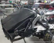
Another.
https://www.jegs.com/i/Five+Star+Ra...riteo&utm_medium=cpc&utm_campaign=retargeting
. Great video, that really put the rear down fast.
https://www.jegs.com/i/AR+Bodies/04...riteo&utm_medium=cpc&utm_campaign=retargeting
This photo is from the video Ozgreen posted and looks similar to the jegs part at the link. Greenwood tribute car by Hendricks.
Another.
https://www.jegs.com/i/Five+Star+Ra...riteo&utm_medium=cpc&utm_campaign=retargeting
Last edited:
rtj
Well-known member
- Joined
- Nov 5, 2011
- Messages
- 3,598
- Reaction score
- 211
At 3:00-5:00 he discusses aero. He explains the dimples. I thought they were passive from the other video, deploying on their own due to low pressure (don’t know why), but it appears to be active. 
[ame]https://www.youtube.com/watch?v=WTF4ACavd1w[/ame]
[ame]https://www.youtube.com/watch?v=WTF4ACavd1w[/ame]
mfain
Well-known member
^^^^^^^^^
Pretty amazing. But I had to laugh - with all that hi-tech equipment, when it came time to test the strength of the wing they used a foose ball table to support one end.
Pretty amazing. But I had to laugh - with all that hi-tech equipment, when it came time to test the strength of the wing they used a foose ball table to support one end.
rtj
Well-known member
- Joined
- Nov 5, 2011
- Messages
- 3,598
- Reaction score
- 211
Yes mfain, kind of an interesting video, some sort of startup business.
This carbon fiber wing below, is pretty unbelievable. I guess when your r&d budget is huge, anything is possible.
[ame]https://www.youtube.com/watch?v=0rtzM-IUAx8[/ame]
This carbon fiber wing below, is pretty unbelievable. I guess when your r&d budget is huge, anything is possible.
[ame]https://www.youtube.com/watch?v=0rtzM-IUAx8[/ame]
Last edited:
mfain
Well-known member
Lots of engine setback allows rad ducts in the camaro. He’s got the swan neck supports on his wing.
https://www.youtube.com/watch?v=aSSYUdqx69o
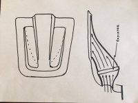
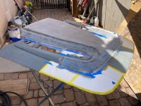
Good video. I have been watching this car in development for years - from early Optima to present. On his hood vents for the radiator, notice the "lips" in front of the discharge holes - provides a low pressure area to help extract the air more efficiently. I am doing something very similar. My engine is well back, so lots of room. Here is a construction shot of the buck for my carbon fiber hood. It has a raised lip across the front (a lot like a '68 big block hood) that will create a low pressure area behind it. The center cowl hood gives me lots of clearance for a large air cleaner on top of the throttle body and very tall fabricated intake. There is duct work built on the bottom of the hood that carries ram air from in front of the radiator (duct goes above the radiator and below the hood skin) back to a box around the TB. I will also put a flapper valve in the back of the cowl that will open if high pressure from the cowl-windshield area exceeds the ram air pressure. Not sure how that will work out. There are outlets on either side of the cowl that exit air from CF ducts that come from the back side of the radiator.
rtj
Well-known member
- Joined
- Nov 5, 2011
- Messages
- 3,598
- Reaction score
- 211
Looks like you have gained lots of CF fab experience building that car. I’m always amazed by CF parts people make.
YouTube isn’t offering many aero suggestions, but this one popped up lately.
I’m actually impressed by F1 cheating efforts, I hadn’t heard of oil burning before. Looks like the rules committee is working on cleaning up wheel turbulence, among other things.
[ame]https://www.youtube.com/watch?v=7nxsT-dey20[/ame]
YouTube isn’t offering many aero suggestions, but this one popped up lately.
I’m actually impressed by F1 cheating efforts, I hadn’t heard of oil burning before. Looks like the rules committee is working on cleaning up wheel turbulence, among other things.
[ame]https://www.youtube.com/watch?v=7nxsT-dey20[/ame]
phantomjock
Well-known member
Pappy -
As always, NICE work.
Just a tip: a pretty good Rule of Thumb on Radiator Duct Design:
I suppose that is something that can be "trimmed" out - which is how I'm planning, a bit of foam, test(?) then 'glass in the shape. Nice catch on the leading edge "lips" on the Camaro's radiator "snorkels" - a nice homage to Dan.
Cheers - Jim
As always, NICE work.
Just a tip: a pretty good Rule of Thumb on Radiator Duct Design:
Inlet area 1/6 area of radiator surface area. [From Walter Korff]
I suppose that is something that can be "trimmed" out - which is how I'm planning, a bit of foam, test(?) then 'glass in the shape. Nice catch on the leading edge "lips" on the Camaro's radiator "snorkels" - a nice homage to Dan.
Cheers - Jim
Last edited:
Similar threads


- Replies
- 3
- Views
- 1K

- Replies
- 93
- Views
- 22K
- Replies
- 31
- Views
- 10K

