Internal Body Aerodynamics

VetteMod - Corvette Restoration, Modding & Performance Forum

Help Support VetteMod Forum:

In lieu of another cuppa'

Chris -

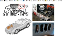
You have had "Eyes-On" these vanes, so maybe you could verify/correct my best guess at their size? I've made my estimate by assuming the bolt heads are about 1/2"/13mm. Do my numbers even look close?

12695ecacbbbae1cd.jpg

I'm interested as I am just now working a plan to incorporate on my SR as a test (mule) to try out. I've made a smallish splitter and could test each in sequence if I have the time. Meanwhile, I'll wait for your ideas on the size.

I'm thinking of making a pair of plates to secure some rubberized edging (you know - from the big box racing supply store).

Thanks.

Cheers - JIm
 
Put me down for a "Thank You, Chris" also. :thumbs:

My goal, as I've stated in the past, is to reduce aero lift and improve the tire grip of my antique, while retaining a stock look when possible. My car is so close to stock appearance that rarely at track days do any (later model) Corvette drivers give my car a second glance. But frequently, after the first or second session, I'm visited by inquiring minds as to why my 50 year old car is filling their mirrors. I don't need to have my self-esteem pumped up by strangers, but I willing admit the inquiries about my car do give me a bit of engineering satisfaction. :wink:
 
Chris -

You have had "Eyes-On" these vanes, so maybe you could verify/correct my best guess at their size? I've made my estimate by assuming the bolt heads are about 1/2"/13mm. Do my numbers even look close?

12695ecacbbbae1cd.jpg

I'm interested as I am just now working a plan to incorporate on my SR as a test (mule) to try out. I've made a smallish splitter and could test each in sequence if I have the time. Meanwhile, I'll wait for your ideas on the size.

I'm thinking of making a pair of plates to secure some rubberized edging (you know - from the big box racing supply store).

Thanks.

Cheers - JIm

Let us know what you find. I'm still trying to figure out if the vanes are there to even out/distribute the air mass under the vehicle floor, or if it is there to divert a portion of the air mass out the lower pressure(?) front wheelwell.

Which, gives me some incentive to measure the relative/differential pressures of under my car and the wheelwell area. Theoretically, my front wheelwells should have a slight low pressure, as the front pace car spoiler directs the side-fender air outward/laterally, pulling air out of the wheelwell volume. Given how dirty my wheels get from brake dust after a day at the track, I have to believe that the general direction of the wheelwell air flow is from undercar to outside the car.
 
Happy to contribute what I can!
Jim, I’d say your numbers are close to what I would have guessed they were.
Not knowing much about how the air is supposed to flow under these cars, I’d say the vanes were designed to direct air out just behind the front wheel, not into it
 
Let us know what you find. I'm still trying to figure out if the vanes are there to even out/distribute the air mass under the vehicle floor, or if it is there to divert a portion of the air mass out the lower pressure(?) front wheelwell.

Which, gives me some incentive to measure the relative/differential pressures of under my car and the wheelwell area. Theoretically, my front wheelwells should have a slight low pressure, as the front pace car spoiler directs the side-fender air outward/laterally, pulling air out of the wheelwell volume. Given how dirty my wheels get from brake dust after a day at the track, I have to believe that the general direction of the wheelwell air flow is from undercar to outside the car.


That is so cool you're filling their mirrors! Now get to PASSING! :rolleyes:


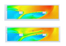
I've found a CFD plot of before and after the vanes added. I can't speak to its "creds" but looks better than my "phony airstream plots" a few pages back!

12695ecaf66a9ac06.jpg

Top one is before vanes and lower with vanes - car nose is on the right - per the previous plots.

Very obvious with the vanes even showing up in the plot. They are clearly directing the air out behind the wheels. I'm not seeing the "Huge" deltas that were in the images I posted of the centerline pressures. Definitely some, and when I look at it some more - there is a change - but over a large area. Surprising the center area just forward of the rear wheels shows some good increase in low pressure too.

69427 - I'd say you are correct looking at this plot of the -no vane CFD, the pressure differential is showing what you have seen trackside, air flowing outwards. Now, I suggest that these ideas have very good opportunities for use on our "antiques." The underbody CFD is not so significantly different from what a C3 could be - but first gotta clean up all that "STUFF." Like add a full belly pan, sort out cooling, a few stealth areo underbody mods - hey you'll be passing them in no time! And they say, "WTF??!!" Yes, the outflow mid body from the big rear facing exit contributes a lot, but centerline and vane mod - do-able.

This has been fun and inspiring. Thanks Guys. And, (scotch in hand), Cheers - Jim
 
YouTube keeps recommending videos. Lots of extra features.

[ame]https://www.youtube.com/watch?v=KClzmArdpDg[/ame]
 
As an Amazon Associate we earn from qualifying purchases. Product prices and availability are accurate as of the date/time indicated and are subject to change.
Inspired by Pappy’s post about the airflow around the oil tank having a notable effect on oil temps got me (and Bob!) thinking...

In my own car, my oil tank sits right next to an “unused” duct from the wheel well to evacuate air out the side gills. My idea was to use the side of the tank as one of the walls of the duct with some aluminum fins welded to the tank to act as a heat sink.

An article I found, with some good info on “forced convection”
It’s fairly short but provides a good starting point for optimizing emissivity, boundary layers and fin density.

https://www.digikey.com/Site/Global/Layouts/DownloadPdf.ashx?pdfUrl=F51974C9A6D544F1A7D8F119514B67FF

Noteworthy points in the article:
Black3 anodizing brings up emissivity considerably, but mostly in natural convection situations

Boundary airflow is a big killer for fin efficiency, turbulence between the fins (to an extent) is more desired

Assuming most of us are using aluminum, 6063 has a slightly higher conductivity compared to 6061

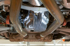
One of the OEM applications I’ve seen use heat sinks is on BMW rear diff housings. Not sure if it’s an ///M car only thing but I’ll see if I can get some pictures of the next one that comes in
attachment.jpg
 
Last edited:
Adding external fins also doesn’t add pressure drop/loss like you would get from an air to oil heat exchanger.
 
More big $$$$$ cars. But, if you want to see new aero, they are the cars to look at.

[ame]https://www.youtube.com/watch?v=TTObTPzRN6s[/ame]
 
In my own car, my oil tank sits right next to an “unused” duct from the wheel well to evacuate air out the side gills. My idea was to use the side of the tank as one of the walls of the duct with some aluminum fins welded to the tank to act as a heat sink.

Kinda', sorta" like this with some fins on the duct?:
12695ca87a147acab.jpg

That seems like a great idea. I guess the fins would be inside the duct to evacuate the heat out as well. One word -- COOL.

Do you have a diagram of how the duct fits in the bay? Intake from bottom - or the bay itself? I like it. Might use it. Two sides - oil cooler on one, transmission cooler on the other. Aluminum sheet - or fiberglass duct? You know me - and what I'll use. ;)

Cheers - Jim
 
It’s not built yet, but the plan is to have a large opening in the back of the wheel well that is ducted out the side gill. “Free” high pressure ambient temperature air. Drivers side will have the oil cooler in it, but I wasn’t able to package any cooler in the passenger side because the oil tank takes up most of the optimal real estate. Carbon is my proposed material... we’ll see how it goes...
 
I’ll start with revisiting the Underbody Strake/Vanes.
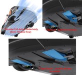
Here is a nice example of the Mercedes Air curtain and it shows the flow field associated with them installed. With some tailoring it could be used to create flow in the location you'd want. Seems a lot easier than creating ductwork (with the attendant internal drag) doesn’t it?

12695ed64e633fde3.jpg

Now (staying in Germany), the Porsche 918 active Aero approach to these vanes:
12695ed64ea483007.jpg

Note the flap is up – or down as needed. I don’t know if operated manually, by temperature, or simply a “Performance Switch.” Hey for near a million bucks for the car it ought to be pretty cool.

Well, it is. I note they also have implemented a cooling/drag reduction set of louvers/doors for the intakes in the nose. Something I recall being discussed here sometime back as an option for the C3. Should be pretty easy.
12695ed64ebc2bde2.jpg


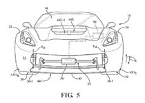
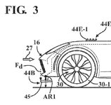
But back in the Good Old USA – we will not be left behind! The following are from a GM patent:
12695ed64ed61cad2.jpg

And the side view for splitter Active Aero and the hood cooling vanes:
12695ed64ef4e9904.jpg
Of course, these all work best with a smooth underbody. But in any case, there is lots of opportunity to “shape up” the Old Girls!

Cheers - Jim

I've been following and considering Active Aero for some time. You'll recall my fascination with the Chaparral cars. I'll start a separate thread in a few days.
 
Last edited:
Inspired by Pappy’s post about the airflow around the oil tank having a notable effect on oil temps got me (and Bob!) thinking...

In my own car, my oil tank sits right next to an “unused” duct from the wheel well to evacuate air out the side gills. My idea was to use the side of the tank as one of the walls of the duct with some aluminum fins welded to the tank to act as a heat sink.

An article I found, with some good info on “forced convection”
It’s fairly short but provides a good starting point for optimizing emissivity, boundary layers and fin density.

https://www.digikey.com/Site/Global/Layouts/DownloadPdf.ashx?pdfUrl=F51974C9A6D544F1A7D8F119514B67FF

Noteworthy points in the article:
Black3 anodizing brings up emissivity considerably, but mostly in natural convection situations

Boundary airflow is a big killer for fin efficiency, turbulence between the fins (to an extent) is more desired

Assuming most of us are using aluminum, 6063 has a slightly higher conductivity compared to 6061

One of the OEM applications I’ve seen use heat sinks is on BMW rear diff housings. Not sure if it’s an ///M car only thing but I’ll see if I can get some pictures of the next one that comes in
attachment.jpg

There are a lot of "apples-to-oranges" in the following observation, but kind-of interesting. My 2015 SS Camaro (LS3 w/8 qts of oil), C6 Z06 (dry sump w/ 10.5 qts), and Viper (11 qts) all use virtually the same liquid-to-liquid oil cooler - a finned aluminum unit. On the Camaro and Z06 the cooler is sandwiched between the engine block and catalytic converter - not much air flow and what there is is probably very hot. The Viper has the unit mounted forward of the engine and directly under one of the open hood vents. The Viper also has a large surface area, flat oil pan that is parallel to the ground and is almost at the same level as the front splitter and belly pan. It probably gets plenty of air flow across its surface. In town driving the Camaro's oil temp is around 225, the Z06 around 220, and the Viper 188-190 degrees. I have never seen over 228 on track in the Viper. I know, different motors and lots of other variables, but I always questioned why GM used a finned oil cooler stuck right next to the catalytic converter.

Pappy

Viper oil cooler.jpg
 

Attachments

  • Viper oil cooler.jpg
    Viper oil cooler.jpg
    71.1 KB
Inspired by Pappy’s post about the airflow around the oil tank having a notable effect on oil temps got me (and Bob!) thinking...

In my own car, my oil tank sits right next to an “unused” duct from the wheel well to evacuate air out the side gills. My idea was to use the side of the tank as one of the walls of the duct with some aluminum fins welded to the tank to act as a heat sink.

An article I found, with some good info on “forced convection”
It’s fairly short but provides a good starting point for optimizing emissivity, boundary layers and fin density.

https://www.digikey.com/Site/Global/Layouts/DownloadPdf.ashx?pdfUrl=F51974C9A6D544F1A7D8F119514B67FF

Noteworthy points in the article:
Black3 anodizing brings up emissivity considerably, but mostly in natural convection situations

Boundary airflow is a big killer for fin efficiency, turbulence between the fins (to an extent) is more desired

Assuming most of us are using aluminum, 6063 has a slightly higher conductivity compared to 6061

One of the OEM applications I’ve seen use heat sinks is on BMW rear diff housings. Not sure if it’s an ///M car only thing but I’ll see if I can get some pictures of the next one that comes in
attachment.jpg

Thanks for the heatsink link. Looks interesting and practical (just skimmed through it at the moment). Page 4 caused me to chuckle. There's a diagram showing the commonality/analogy of heat flow and electrical current flow. My engineering experience is predominately electrical, and I've worked out a lot of designs/problems on my car by figuring out an electrical solution (changing current flow, voltage/pressure issues, capacitance/surge-volume affects, etc) and then converting that electrical solution to the mechanical analog on the car.

Perhaps not the most efficient way to do things, but that's how my brain is wired.

Every time I look at the batwing on my car, I always think about what additional gear lube cooling ability I could have done to the batwing if I had taken the time to weld a bunch of fins onto it. The stock batwing is certainly a better conductor of heat than the original cast iron cover, but it would be nice to pull some more heat out there, short of adding the complexity of a pump and heat exchanger.
 
.....Every time I look at the batwing on my car, I always think about what additional gear lube cooling ability I could have done to the batwing if I had taken the time to weld a bunch of fins onto it. The stock batwing is certainly a better conductor of heat than the original cast iron cover, but it would be nice to pull some more heat out there, short of adding the complexity of a pump and heat exchanger.

I must have hours of searching in trying to find C4 road race guys that have issues with diff cooling (with no pump). I havent seen anyone mention a thing, which could be that, like you said, the batwing is such a large heatsink that it dissipates heat really well. I plan on collecting some temperature data on my stock C4 diff once I get the car on the road. Would be interesting to see any difference with a heatink ala the BMW diffs
 
.....Every time I look at the batwing on my car, I always think about what additional gear lube cooling ability I could have done to the batwing if I had taken the time to weld a bunch of fins onto it. The stock batwing is certainly a better conductor of heat than the original cast iron cover, but it would be nice to pull some more heat out there, short of adding the complexity of a pump and heat exchanger.

I must have hours of searching in trying to find C4 road race guys that have issues with diff cooling (with no pump). I havent seen anyone mention a thing, which could be that, like you said, the batwing is such a large heatsink that it dissipates heat really well. I plan on collecting some temperature data on my stock C4 diff once I get the car on the road. Would be interesting to see any difference with a heatink ala the BMW diffs

FWIW I've never measured the actual gear lube temperature in my differential (I'm still using the C3 differential in front of the D36 batwing), but I've taken a few measurements of the batwing surfaces with my IR temperature gun. The cover area behind the ring gear, while the hottest, has never been hot enough that I considered sitting out a session to let it cool down. I credit that to several things: Breaks between the 15-20 minute sessions, no super long straights at WOT, and only a modest horsepower engine powering the drivetrain.
 
This is interesting. Basically he is making the spoked mag into a centrifugal compressor. Even though he says the opposite. Look at a centrifugal compressor disk if you want to see why. That does cool the brakes and does lower the pressure under the car, which explains why the wing needs less angle.


[ame]https://www.youtube.com/watch?v=dpje3x4s9U0[/ame]

This is obviously a well designed part, he just doesn’t have the facts straight.
 
I've been trying for years to come up with a set of extraction fans for my track wheels, but haven't come up with anything that would seem to work well or package well. I'd sure love to be able to keep the rotors cooler and pull out some of the underhood and undercar air.

I haven't given up yet.
 
[ame]https://www.youtube.com/watch?v=piWgv60DTSY[/ame]
 
Okay, this is overly complicated, probably because of some rule that doesn’t allow control valves for aero devices. So the driver activates a fluid switch by blocking a pipe with his hand.

They stall the wing in such a way that even though lift drops, drag drops significantly. For use on straights, allows running high downforce wing.


[ame]https://www.youtube.com/watch?v=Ai3O03S55YI[/ame]
 
Interesting. The side pod diffuser tunnels that they show as banned early in the video are what I have on my '56 - between the outside of the frame rail and the inside of the side body skirt. I have the rear wing adjusters on a bellcrank assembly with the future possibility of adding an aircraft trim motor to control the wing AOA. It would take something faster acting than a trim motor to rapidly change the angle in order to create drag for decel, especially after trimming out the AOA for low drag on a straight and then going back to high downforce for a corner. I see the potential to get yourself in a lot of trouble. I guess with F-1 type money you can overcome these things.

Diffuser Tunnels.jpg
 
mfain, I think Phantomjock posted an active control system for wings. It was a year or two ago.

Sounds like the tunnels should work then.

Anxious to hear/see video of your car.
 
Pappy -

Like to hear more about your Lotus 78/79 inspired side tunnels. I have had side tunnels in the SR side pods for about 3 years now. Built as 10 degree and 20 degree. Haven't"swept" with an airfoil section - just straight, flat ceilings. Butt dyno says it works well. Plan has foam and glass inserts, not built yet.

I had side skirts (Chaparral-style) and that was like the car was literally on rails. They were 2 inch aluminum, and Tech missed seeing them as we teched on grass. Pulled them after a weekend to stay "legal."

Faster motor? Maybe a servo is the answer. Placement of the control arm is key to keeping the loads down. On my back burner is an Active Aero module to be semi-autonomous, sort of wings level trim, that "paddles off" under acceleration (DRS) and under braking - increases. I'm sure we have some brighter EEs here than me.

I have planned a complete testing of some of the components ion the SR. It has been the Mule for the "vette mods, and once I get a few bugs sorted out and the test done - I'll share too.

Cheers - Jim
 
Some nice visualization.

The best image is at 1:16, but you almost have to pause it.

[ame]https://www.youtube.com/watch?v=cGrFN2jZeY8[/ame]
 
Pappy -

Like to hear more about your Lotus 78/79 inspired side tunnels. I have had side tunnels in the SR side pods for about 3 years now. Built as 10 degree and 20 degree. Haven't"swept" with an airfoil section - just straight, flat ceilings. Butt dyno says it works well. Plan has foam and glass inserts, not built yet.

I had side skirts (Chaparral-style) and that was like the car was literally on rails. They were 2 inch aluminum, and Tech missed seeing them as we teched on grass. Pulled them after a weekend to stay "legal."

Faster motor? Maybe a servo is the answer. Placement of the control arm is key to keeping the loads down. On my back burner is an Active Aero module to be semi-autonomous, sort of wings level trim, that "paddles off" under acceleration (DRS) and under braking - increases. I'm sure we have some brighter EEs here than me.

I have planned a complete testing of some of the components ion the SR. It has been the Mule for the "vette mods, and once I get a few bugs sorted out and the test done - I'll share too.

Cheers - Jim

Hey Jim,

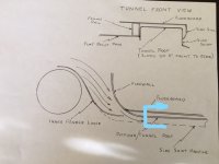
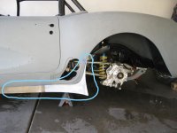
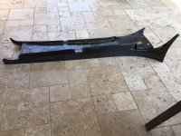
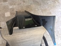
I have the tunnels/belly pan/diffuser off the car right now doing some undercarriage work, but I was able to take a couple of photos to show how the diffuser tunnels are set up. The sketch shows how the tunnels blend into a rounded leading edge that is actually an extension of the firewall. The area highlighted at the rear is the portion of tunnel that is shown in the following photos. Photo 2 shows the side skirt (under construction at the time of the photo) and the third photo is of the tunnel assembly with side skirt. The last photo shows the actual diffuser tunnel from the back looking forward - inverted wing profile with a 12 degree diffuser discharge angle (including vehicle rake).

56 Corvette Tunnel 4_LI.jpg

56Corvette Side Skirt Under Construction_LI.jpg

Tunnel 2.jpg

Tunnel 3.jpg
 
Pappy the detail on your car never ceases to amaze me!

I’m interested to see what (if anything?) you’ve done to smooth airflow going under the rear suspension out the rear of the car
 
Pappy the detail on your car never ceases to amaze me!

I’m interested to see what (if anything?) you’ve done to smooth airflow going under the rear suspension out the rear of the car

Got a couple of tricks up my sleeve. I originally had a diffuser that ran from just behind the rear axle to the rear of the car. It wasn't very pure from a downforce perspective - too short and somewhat convoluted with provision for the exhaust tips. There are a couple of photos of that original diffuser in post 110, page 11 of this thread. After I changed rear suspension I modified that piece to stay in place, but I am now constructing a second diffuser that will run from just in front of the front of the differential to the rear of the car. It will be below and supported by the rear strakes on the original (upper) diffuser and there will be a 4 inch vertical gap between the two. Air from the area of the spinning axle shafts, from the trans and diff cooler fans, and the exhaust will pass between the diffusers. The bottom diffuser will be for pure aerodynamic function - adjustable diffuser divergence angle with long vertical strakes very similar to my Viper ACR.

Pappy
 
Back
Top