Grafting a C5 rear suspension on C3

VetteMod - Corvette Restoration, Modding & Performance Forum

Help Support VetteMod Forum:

phantomjock

Well-known member
Joined
Sep 2, 2009
Messages
1,925
Reaction score
103
City & State/Province
Retired Again!
So the challenge:

"How to Mount a C5 (or similar double wishbone) rear suspension - and elminate the trailing arms?"

TT has been working on his set up using double wishbones and I'll show some of those in the my next post.

BUT: I'm not looking to build the wishbones and hub carriers as he has done, but understand how to mount C5 Rear Suspension Components to the C3 chassis. This will be a bit of a "think piece" with the aim of geting ready for an eventual build. I haven't ditched my Giovanni - just yet. And I am quite invested in the 4.11 rear end, dual mount spring, etc to just yet move away from my current suspension. BUT, time will tell.

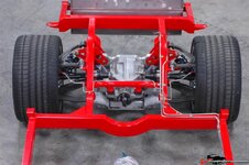
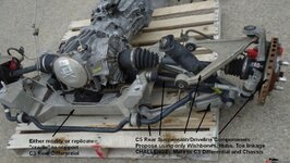
I'd start with the C5 rear suspension components:
12694ec7f8de1ed3d.jpg

At first look, I think the most useful bits are the Hubs, Wishbones, Toe Adjust struts, and Sway Bar. Maybe useful--the cradle, but I doubt the C5 cradle would accomodate a C3 rear differential. Also, what half shafts to use? Custom, or modify C3/C5? To be determined. Complete rear suspension bits are available for $1000-1500. But how to mount to a C3 frame?

While on holiday (first in several years) I found myself a few miles from the FactoryFive's main facory location. In preparation for a visit - I did some research on their website and found an interesting approach for their Type 65/Daytona Cobra Coupe:
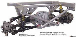
12694ec7f8e126dc0.jpg
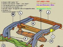
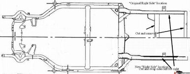
The cross bracing and lower mount for the rear diff would need to include an upper mount for a C3 diff. But the approach looked like it has promice. I'm not interested in using Mustang parts - so I'd stick with C5 and adopt the approach. That got my mental juices flowing and I started messing around with the C3 Frame Diagrams:
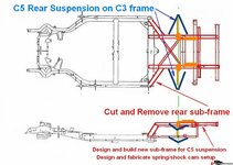
12694ec7f8e1ecd8a.jpg

[Unfortunately, my laptop only has "paint-like" capabilities and not my CAD programs. So, please excuse the neccessary clumsliness of the diagrams.]

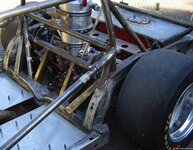
Then, I rememberd seeing a similar approach on a Tube Chassis - but it is a C4 Suspension - still not the"Holy Grail."
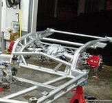
12694ec7f8e2e831c.jpg

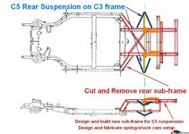
Wait! What if I cut and reused pieces of the original C3 frame?
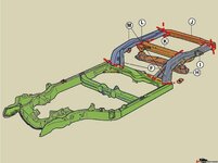
12694ec7f8e320bb2.jpg

Or, in closeup:
12694ec7f8e4013af.jpg

looking at the mirrored positions:
12694ec7f8e4db7c8.jpg

And, in a reassembled diagram - waiting for the key components, additional structural components, and subframe to support a C3 rear Diff and C5 suspension bits:
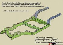
12694ec7f8e583d5c.jpg

One advantage/disadvantage to this approach is it will require some mods to the interior. The rear "arms" will be substantially closer together, and will require the interior to be "Tubbed," in the lingo of "Pro-Touring." That will offer the opportunity for more Meat on the rims too.

While doing some "research" (surfing), I came across this rear stub on the Spanish "Tramontana:"
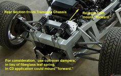
12694ec7fab3907eb.jpg

The Coil-Overs could be mounted "awthwarts" or forward. In either case, interior mods to access the adjustability features offered by using them. Getting the Cam designed correctly and sizing the actuator rods will be important too (avoid Euler buckling in the strut.)

Comments? Thoughts? I'd appreciate any feedback.
Is this a path already well trodden? I know TT has built his double wishbone rear suspension components on his C3, but the pictures don't offer enough information to "reverse engineer" - err, copy directly. And, I'm not interested in building the wishbones - but adapring the C5 to the C3!

I'd really, really greatly appreciate any CAD drawings of C5 rear suspension components, C3 Chassis, rear diff etc.
I'd gladly assemble the drawings in SolidWorks or RHINO, based on what you have available.
I need to get back to using those, its been a while.
But it will be a few weeks until I'm back at the other PC.

Cheers - Jim
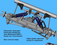
 
Twin Turbo's Double Wishbone work

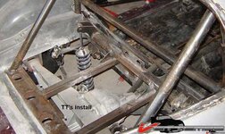
Its tough to find anything that TT hasn't tried before. Here is a shot of his layout for a double wishbone rear suspension setup on a C3 Chassis:
12694ec7fab4a5352.jpg
Its a great CAD drawing I'd like to get a copt of -- HINT HINT!

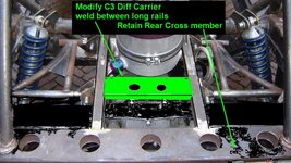
I found a shot and did some "paint-by-numbers" and it appears possible to use a section of the C3 rear Diff Carrier and weld it to the 2 longutidnal rails he has built. The Florecent Green stub represents the center section of the C3 carrier.
12694ec7fab5808fc.jpg

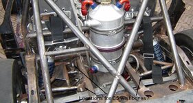
Using this approach, would let me use the C3 differential. His design and build have included lowering the fuel cell and there is good clarity in the image below showing the rear suspension "Stub" he created:
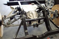
12694ec7fab67f530.jpg

Here is another shot showing the wishbones he built:
12694ec7fab76db53.jpg

I am not interested in building the wishbones, but incorporating the C5 components, wishbones, hubs, etc.
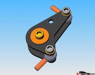
Here is a close up of his CAM implementation for the coil-overs:
12694ec7fab8786f4.jpg
Hint Hint..any chance of getting a copy of this data too??

I'd like more information on that approach and it appears in the final build he went for a more conventional approach. You can see the complete "Stub" in this shot:
12694ec7fab956f24.jpg

As an added point it integrates well with the rollcage too.

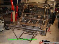
Here is a good shot showing his final setup:
12694ec7faba34c09.jpg

Well, his project has been idle for a bit of time, but maybe it is what was purcolating in my mind as I started with:
12694ec7fabb22e70.jpg

So, here again a chance to review and comment - and help improve the road handling of the C3, by grafting a C5 rear suspension to it.

It will be a bit before I am ready to tackle this effort - It will require me to first finish my C3 project, find a spare frame, some C5 suspension bits, and with time all your encouragements!

Cheers - Jim
 
I think if you have a complete C5 or C6 suspension (front and rear) incl the aluminum cradles it's relatively simple to fabricate the steel portion that needs to be welded to the C3 frame that the cradles can bolt to.... C3 body off of course....

Now.... having a C6 I can tell you the handling is absolutely awesome, it would be great having that in a C3. It is a lot of work and time.... time is the limiting factor or me :)
 
I kicked around putting a C5 rear suspension on my '69, but as was mentioned above, it doesn't package well. I didn't want to cut up the original bodywork to get the A-arms in there, so I went with a narrowed C4 rear.

If I was doing this project again (assuming I found a donor car to cut up) I would widen the body about an inch or inch and a half on each rear fender (enough to tuck slightly wider tires, but not enough width to be very noticeable, as in a C6 Z06). I'd then narrow/reweld the C5/C6 aluminum rear suspension carrier "X" inches to bring the suspension in (with whatever tires I had planned to use) to fit under the new fenders. The rear frame rework (simple fabrication and steel welding) looks to be easy to do to fit the C6 suspension (even when narrowed), as long as the body glasswork isn't a hinderance.

JMO
 
Get a Viper Dana44 center section set up for CV joints and you have the solition for that too. It looks like that's what street shop did too, the front mount ears on that thing, just aft of the pinion is what a viper has.
 
As an Amazon Associate we earn from qualifying purchases. Product prices and availability are accurate as of the date/time indicated and are subject to change.
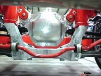
BBShark - I had just found the Street Shop setups this morning!

Looks good - and their approach of using their own custom fabricated rear diff cover make mating to their frame a cinch.
12694ec968259ff8a.jpg

Now all that is needed is the dimensions, some materials, a bit of welding, oh yeah, a pile of money. But it looks like a reasonably affordable mating and much improved performance. Even if you'd loose some grocery options!
12694ec967df14d7b.jpg
Cheers - Jim
 
Last edited:
Now all that is needed is the dimensions, some materials, a bit of welding, oh yeah, a pile of money. But it looks like a reasonably affordable mating and much improved performance. Even if you'd loose some grocery options!
12694ec967df14d7b.jpg
Cheers - Jim[/QUOTE]

If you have to do floor mod's to get that to fit under a C3 why not go a step further and use a C5 trans axle and all?
 
Now all that is needed is the dimensions, some materials, a bit of welding, oh yeah, a pile of money. But it looks like a reasonably affordable mating and much improved performance. Even if you'd loose some grocery options!
12694ec967df14d7b.jpg
Cheers - Jim

If you have to do floor mod's to get that to fit under a C3 why not go a step further and use a C5 trans axle and all?[/QUOTE]

It's my impression that the shorter C3 wheelbase would end up putting the C5 transmission in your right armpit.
 
Pretty Sweet -
As to Camber - from the Instructions:
5. LOWER CONTROL ARMS
The lower control arms are attached to the housing and the pinion plate with the tie bars as shown, using the 5/8” bolts, nuts and washers supplied. Be certain to use washers between the rear adjusters and the housing. Shim washers are used between the pinion plate and the front adjusters to fit the arms. Do not tighten the bolts and nuts yet, as the camber is adjusted here by turning the adjusters in or out. The arms should be set with the adjusters equal, to make the arms straight out and parallel for now.

thum_12694eca1f47a623a.jpg

It is interesting with the inboard brakes - they didn't choose to use a cam actuated linkage to inboard coilovers. Maybe that is Rev 2.0.
Also note - STARTING PRICE is $7999! Goes up from there - The base unit is a 4.11 though.

BTW - They also have dropped front spindles (2") for 67-60 Camaro, 67-79 Nova, & 64-72 Chevelle. Aren't the C3 front spindles Nova's - or is that the stock A-Arms?

Cheers - Jim
 
Last edited:
Well this is interesting, but just touches on a subject I'm curious about. Is there an advantage to CV joints over U-joints?
 
Well this is interesting, but just touches on a subject I'm curious about. Is there an advantage to CV joints over U-joints?

The CV axles are smaller and lighter (I think).

But, if you were using a Viper rear and C5 hubs, would you have to make some special axle that had a Viper joint and a C5 joint? Sounds like money $$$$$$$$$$$$$
 
Is that the only advantage? I'm not knocking it but it seems to me that a smaller axle would be a disadvantage. I mean aren't the 3" halfshafts supposed to be better/heavier duty than the 2.5" halfshafts?
 
The Drive Shop (and probably others) builds CV-jointed axle shaft good to 1000+ horsepower. CV joints do not have the internal friction of a splined shaft slip joint using u-joints, and are not as prone to giving an abrupt suspension geometry change if they bind under heavy load.

Pappy
 
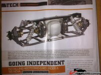
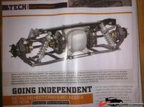
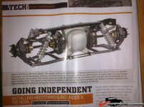
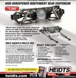
how about this??? It's only $8000 and it sure looks cool with the brake rotors inboard.... :D

214ec9aa6ae7245.jpg

How do you adjust the camber (without removing bolts and stuff) on that setup?

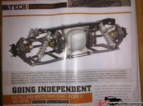
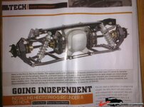
The article quoted is in the Jan 2012 issue of Super Chevy. If you look at the article or the Heidt's add on page 59, you will see there is another link that runs from the outboard end of the lower control arm forward to a chassis pick-up point. This arm absorbs the forward and rearward thrust to prevent the lower control arm from flexing fore/aft. The lower control arm also controls the toe (note no toe link). The only thing that makes me nervous is the single upper link with no forward link to prevent forward or aft movement of the top of the spindle. With enough acceleration or braking force, you might twist the lower control arm enough to get some movement. I still prefer two forward links to take the driving and braking forces (with adjustable instant center for anti-squat/anti-dive control), an upper and lower link above and below the axle with moment center height and camber adjustment, and a rear toe link. This configuration, similar to the old Can-Am and original GT-40 cars, when run with newer, stronger CV joints and axles and ZR1/SKF wheel bearings should perform well. Another very interesting article you might want to look at is on page 68 on the Nov 2011 issue of Camaro Performers. That article shows installation of a 9-inch Ford-based IRS differential set up with CV joint axles for the new Camaro. It would be very easy (LOL) to adapt that differential housing to an early Corvette by welding different mounting brackets and provisions for the upper and lower links. My $.02 worth.

Pappy
 
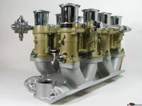
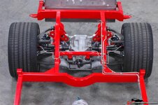
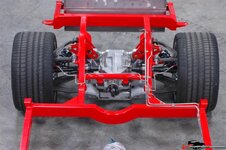
Nice - but just like using an XKE rear end - mixing pedegree! But what can I say - I'm mounting 4x48 Webbers on a SBC! Downdraft - not sidedraft, like the GS! BTW - didn't they put a circle around it - to cleary identify the Problem? (FORD)

Anyhow -I spent a great afternoon at the FactoryFive shops, showroom etc. Great products, fantastic work environment, and each employee focused on getting their customer/guest the info needed. Powdercoating is done off site - but all the fiberglassing, welding and basic assembly on site. Did a full tour of the factory and a heap of pics if there is interst - I'll hang on my pics page.

I spent a lot of time evaluating and "shooting" the rear end on the GTR - and their frame that has a drop in of the wishbones and toe control from the C5 - wich is really germaine to this thread. I'll post when "developed."

For me @ 200# and 6'3" the Daytona Type 65 - just fits - but surprisingly the Pontiac Solstice fits better, the Hot Rod - ok but not my style, and the roadster MK4 - too short in the foot box for long term use. The GTR - while sweet, entry/exit tougher still - the overhead cage a bit of effort - halo and all.
But, I have some nice AIRBOX pics that will be will be forthcoming along with the rear IRS showingthe C5 bits installed.

Cheers - Jim
 
What kind of downdraft intake? I have a nos SBC "ultra" intake somewhere, set up for 48 IDAs.
 
The upper link is only bent for frame clearance. The coilover only needs to be to the rear to avoid twisting the LCA. And what if you were to add an upper watt's link like this and move the coilovers forward?
http://s350.photobucket.com/albums/q401/acmjg/?action=view&current=MOV04917.mp4

Also to stabilize the C3 carrier add links like this fore and aft with L/R heims.
http://www.todaysauto.net/musclecars/badboy/splash-showtruck(19).JPG

how about this??? It's only $8000 and it sure looks cool with the brake rotors inboard.... :D

214ec9aa6ae7245.jpg

How do you adjust the camber (without removing bolts and stuff) on that setup?

The article quoted is in the Jan 2012 issue of Super Chevy. If you look at the article or the Heidt's add on page 59, you will see there is another link that runs from the outboard end of the lower control arm forward to a chassis pick-up point. This arm absorbs the forward and rearward thrust to prevent the lower control arm from flexing fore/aft. The lower control arm also controls the toe (note no toe link). The only thing that makes me nervous is the single upper link with no forward link to prevent forward or aft movement of the top of the spindle. With enough acceleration or braking force, you might twist the lower control arm enough to get some movement. I still prefer two forward links to take the driving and braking forces (with adjustable instant center for anti-squat/anti-dive control), an upper and lower link above and below the axle with moment center height and camber adjustment, and a rear toe link. This configuration, similar to the old Can-Am and original GT-40 cars, when run with newer, stronger CV joints and axles and ZR1/SKF wheel bearings should perform well. Another very interesting article you might want to look at is on page 68 on the Nov 2011 issue of Camaro Performers. That article shows installation of a 9-inch Ford-based IRS differential set up with CV joint axles for the new Camaro. It would be very easy (LOL) to adapt that differential housing to an early Corvette by welding different mounting brackets and provisions for the upper and lower links. My $.02 worth.

Pappy
 
Last edited:
Ralphy,

That upper Watts link is interesting. It makes the upper end of the spindle travel in a pure vertical line while the lower forward link swings the bottom of the spindle in an arc -- this would slightly change the caster with suspension travel, but that should not be too significant on the rear suspension, unless you end up with dead zero caster, in which you might pick up a "shimmy". Using only an upper forward link (instead of the Watts link) would be similar to using a panhard bar instead of a Watts link to center a straight axle. I will have to give some thought as to what the Watts link does to the instant center as the spindle travels up and down -- might be some affect on anti-dive/anti-squat (good or bad??). In any case, I think an upper forward link is required to stop any movement of the top of the spindle fore or aft during hard acceleration or heavy braking. By the way, the lower forward link in your posted video is very similar to the one on the Heidt's IRS. The upper Heidt's link is indead bent for clearance -- not too good of an idea since the link is in compression and the bend might allow some flexing. I'm still dreaming of cornering forces in excess of 1.5 lateral g with big, wide, sticky tires and 850 horsepower trying to twist the suspension into knots -- I tend to be on the side of "overkill". LOL

Cheers,
 
The Jag setup is an interesting one and I spent a few hours looking at a site pretty much devoted to them. The "dogbone" instead of "wishbones" seems so, well "Lucas-like," but simple in approach. The inboard brakes raise a lot of discussion on the sites where guys are converting their 2nd gen suspensions. Potential difficulty to access to change pads, unsprung weight, cooling, etc. And - hey- if it is going to cut up the interior anyway -- WHY NOT?

TT - here is a shot shamelessly swiped from Jim Ingleese's site:
thum_12694ecb7590cd859.jpg
My rig is similar - carb bodies will be gloss black when completed, 1/2 way through polishing the aluminum intake manifold. When assembled and on the SBC - I'll take some assembled pics.
Jim and I have been wondering the make of my manifold - it may be a "Fast Freddy" from the west coast. Similar style to the one above - but with "cooling fins" groved into the topside between the IRs and a large rectangle and "W" in the casting too. It has the below deck vacuum set up - but I won't use it much with hydroboost and a crank trigger Electromotive setup. I was told it was manufactured by Weber - but no indication (pn/sn/etc) on the manifold casting.

That wasn't tooo far astray - even used "IRs" when talking Carbs(albeit, independent runners!)

Cheers - Jim
 
Pappy,
If you like overkill, you should love this build. Able to withstand 1,400 HP they say. LCA's are 1 5/8", uppers are 1 1/4". If you select the, I think 600HP half shafts, do you need that heavy of control arm's? LOL!


http://www.roadstershop.com/images/documents/irs_details.pdf

Also the previous video shows with the guy using the Jag dog bone. Again I would toss it for an aftermarket wishbone and remove the forward link. Then add the watt's. The watt's was added to avoid wheel hop. Believe it or not, there are guys running with only the dog bone! Ouch!
 
Last edited:
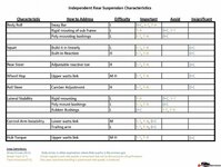
IRS Characteristics Chart

In my crawling of the web - came across this chart.
Ought to raise some intersting discussion opportunities:
12694ecbdd56a694f.jpg

Ralphy - this will look a little familiar ;)
Cheers - Jim
 
Last edited:
Back
Top