phantomjock
Well-known member
We’ve a lot of good discussions that have wound up in the “Internal Aerodynamics” thread. The topic I’m bringing is focused on EXTERNAL MODIFICATIONS, so thought I’d start as such.
Rather than ask to realign any of those items, I have done a quick catalog of EXTERNAL AERODYNAMICS.
Other Corvette External Aero Threads:
FRONT END LIFT:
FRONT SPOILER VS AIR DAM:
REAR SPOILERS:
FRONT SPOILER:
https://www.vettemod.com/search/551033/?q=front+spoiler&o=relevance
FENDER LOUVERS:
https://www.vettemod.com/search/551034/?q=fender+louvers&o=relevance
WING:
https://www.vettemod.com/search/551030/?q=WING&o=relevance
DIFFUSER:
https://www.vettemod.com/search/551031/?q=Diffuser&o=relevance
SIDE SKIRTS:
https://www.vettemod.com/search/551036/?q=side+skirts&o=relevance
First, I wanted to address the aerodynamic challenges of an early model C-3 Corvette.
Specifically the “flying Butress” design rear deck.

I had previously “labeled” this image, and I wanted to see if I could visit the same issues in a CF model. I have teaching myself CFD and it is a “natural” addition to my other aero background(s).
A simple model used for many CFD studies is the Ahmed. It is a relatively simple shape that students us to learn CFD and then run a model in the wind tunnel to verify and compare the results.
This model represents a C-3 Variant of an Ahmed model:

I loaded up the model int the software and ran some profiles. I used a range of speeds, and 40 meters per second is a pretty good one as it is pretty close to 90 mph. I ran the models at full scale to avoid any conversions and Reynolds Number issues.
This is the output of one of the runs:

You’ll note the similar areas of turbulence on the rear deck. Because this “slice” does not include the vehicle sides, the turbulence around the wheel mirror and outside of the rear deck is not shown.
The Baldwin/Motion modifications are often suggested as an aerodynamic choice to improve the airflow. This custom mod is an interpretation of that approach:

My block model CFD run to compare is here:

Easy to see the turbulence on the rear deck in this run has been eliminated.
Next, I wanted to see what the run would look like with a wing on the rear:

I won’t offer any conclusions regarding this run. My version of the software is limited to 1000 iterations, and it is difficult for the program to reach convergence with that limit. But it does give some general ideas. The software also restricts the number of streamlines and other bits of useful information – but it is free and a great learning tool.
One of our own forum members did a rear deck mod similar but not as drastic as a full Baldwin mod.
Here is denpos’:

“Back in the day” Ecklers offered parts to effect such a mod. One I think would be interesting and offer a CAD/CFD challenge is the rear Louvers seen on this catalog page:

Meanwhile, I have prepared a set of 18-20 variations on a C-3 early model. These include the Baldwin, a diffuser, splitter, air dam, etc. A smooth sample of one of the Motion versions is here:

For these I’ve removed all the trim, mirrors, bumpers, door handles, and blocked off the front radiator inlets. The software is much easier to run with fewer such complications. Perhaps less realistic – but close enough to compare these various mods.
I’m putting my pencils (and mouse) down on this project for a bit. I’m preparing the headers for ceramic coating. Then I need to get the aluminum cut for the belly pan, followed by some interior work. Wiring, fuel and brake lines, etc., etc. I just got the parts in to resolve a bump steer with the steering. These activities will be all in Elvira’s thread.
Cheers - Jim
Rather than ask to realign any of those items, I have done a quick catalog of EXTERNAL AERODYNAMICS.
Other Corvette External Aero Threads:
FRONT END LIFT:
I was going to post this in the tech section, but that area doesn't look like it gets much attention.
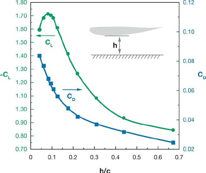
A fellow VM member (I'll let him identify himself if he wishes) mentioned that the lift at speed on his car is due to the bodywork area in front of the radiator. While I don't have any actual data myself, it seems reasonable that this area would contribute to the front end lift. Given that this area (actually, a volume) in front of the radiator is a diffuser, changing high velocity air into pressure (to increase efficiency of airflow through all the radiator fins), the slight pressure gain...
A fellow VM member (I'll let him identify himself if he wishes) mentioned that the lift at speed on his car is due to the bodywork area in front of the radiator. While I don't have any actual data myself, it seems reasonable that this area would contribute to the front end lift. Given that this area (actually, a volume) in front of the radiator is a diffuser, changing high velocity air into pressure (to increase efficiency of airflow through all the radiator fins), the slight pressure gain...
- 69427
- Replies: 95
- Forum: Classic Corvettes
FRONT SPOILER VS AIR DAM:
The factory spoiler on my 69 is long gone. I am having bodywork done after many years of damage. So, I thought this might be a good time to replace the spoiler.
Just so you know, the car is 50% street driven and 50% track time, mostly HPDE and Time Trials.
I could get the regular spoiler as shown in the pic.
But I do run air ducts to keep the brakes cooler on fast tracks and therefore the Air Dam with holes for ducting is a plus.
I have two concerns:
1) What will they do to the handling of the car?
2) With the F-41 springs up front and the car lowered one inch, will these become...
- T-Guy69
- Replies: 2
- Forum: Classic Corvettes
REAR SPOILERS:
Has anyone done the research regarding effective rear spoilers for C3s? My working hypothesis is the spoiler would have to be above the roofline to truly be effective (don't care about whether or not it's a ricer look, but it must function)
While the gas tank is out, I want to brace the deck for a spoiler.... thus the timing of the question
While the gas tank is out, I want to brace the deck for a spoiler.... thus the timing of the question
- SuperBuickGuy
- Replies: 115
- Forum: Classic Corvettes
FRONT SPOILER:
https://www.vettemod.com/search/551033/?q=front+spoiler&o=relevance
FENDER LOUVERS:
https://www.vettemod.com/search/551034/?q=fender+louvers&o=relevance
WING:
https://www.vettemod.com/search/551030/?q=WING&o=relevance
DIFFUSER:
https://www.vettemod.com/search/551031/?q=Diffuser&o=relevance
SIDE SKIRTS:
https://www.vettemod.com/search/551036/?q=side+skirts&o=relevance
First, I wanted to address the aerodynamic challenges of an early model C-3 Corvette.
Specifically the “flying Butress” design rear deck.
I had previously “labeled” this image, and I wanted to see if I could visit the same issues in a CF model. I have teaching myself CFD and it is a “natural” addition to my other aero background(s).
A simple model used for many CFD studies is the Ahmed. It is a relatively simple shape that students us to learn CFD and then run a model in the wind tunnel to verify and compare the results.
This model represents a C-3 Variant of an Ahmed model:
I loaded up the model int the software and ran some profiles. I used a range of speeds, and 40 meters per second is a pretty good one as it is pretty close to 90 mph. I ran the models at full scale to avoid any conversions and Reynolds Number issues.
This is the output of one of the runs:
You’ll note the similar areas of turbulence on the rear deck. Because this “slice” does not include the vehicle sides, the turbulence around the wheel mirror and outside of the rear deck is not shown.
The Baldwin/Motion modifications are often suggested as an aerodynamic choice to improve the airflow. This custom mod is an interpretation of that approach:
My block model CFD run to compare is here:
Easy to see the turbulence on the rear deck in this run has been eliminated.
Next, I wanted to see what the run would look like with a wing on the rear:
I won’t offer any conclusions regarding this run. My version of the software is limited to 1000 iterations, and it is difficult for the program to reach convergence with that limit. But it does give some general ideas. The software also restricts the number of streamlines and other bits of useful information – but it is free and a great learning tool.
One of our own forum members did a rear deck mod similar but not as drastic as a full Baldwin mod.
Here is denpos’:
“Back in the day” Ecklers offered parts to effect such a mod. One I think would be interesting and offer a CAD/CFD challenge is the rear Louvers seen on this catalog page:
Meanwhile, I have prepared a set of 18-20 variations on a C-3 early model. These include the Baldwin, a diffuser, splitter, air dam, etc. A smooth sample of one of the Motion versions is here:
For these I’ve removed all the trim, mirrors, bumpers, door handles, and blocked off the front radiator inlets. The software is much easier to run with fewer such complications. Perhaps less realistic – but close enough to compare these various mods.
I’m putting my pencils (and mouse) down on this project for a bit. I’m preparing the headers for ceramic coating. Then I need to get the aluminum cut for the belly pan, followed by some interior work. Wiring, fuel and brake lines, etc., etc. I just got the parts in to resolve a bump steer with the steering. These activities will be all in Elvira’s thread.
Cheers - Jim


") Last week I added an additional one inch lower strip to it for track days. It comes off with six bolts for street use. Behind the airdam I have about four feet of Lexan bellypan to discourage air from just balling up in front of the radiator or up into the engine compartment. The sides of the Pace Car spoiler seem to do a decent job of causing a low pressure zone at the wheel faces, pulling air (and brake dust) out to the sides. I've got some air directors on the lower control arms to direct some of the undercar air up into the brake rotor centers for cooling. (I felt like this was kind of a hillbilly modification until a few years later I saw a similar factory setup on C6Z06 Corvettes.
Last week I added an additional one inch lower strip to it for track days. It comes off with six bolts for street use. Behind the airdam I have about four feet of Lexan bellypan to discourage air from just balling up in front of the radiator or up into the engine compartment. The sides of the Pace Car spoiler seem to do a decent job of causing a low pressure zone at the wheel faces, pulling air (and brake dust) out to the sides. I've got some air directors on the lower control arms to direct some of the undercar air up into the brake rotor centers for cooling. (I felt like this was kind of a hillbilly modification until a few years later I saw a similar factory setup on C6Z06 Corvettes.  ) So far I've never had any issues with overheating the brakes.