'69 suspension upgrade

VetteMod - Corvette Restoration, Modding & Performance Forum

Help Support VetteMod Forum:

69427

The Artist formerly known as Turbo84
Joined
Mar 30, 2008
Messages
3,080
Reaction score
42
City & State/Province
Clinging to my guns and religion in KCMO.
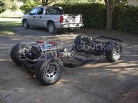
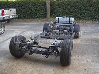
Got the frame done as far as I could go prior to slipping under the body again. The front frame horns will be finished once the body is positioned.
IM001053.jpg

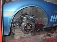
Got the body sitting on the frame. The work right now involves shimming the body mounts, and cutting/modifying the front bumper brackets and lower radiator crossmember mounts. The sway bar sits higher than the previous C3 location, so that required modifications to the brackets. The steering column to steering rack linkage measurements are now possible to do.
IM001056.jpg

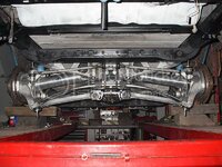
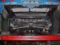
The rear area looks basically okay, although there were a couple items that slowed me down. As I was lifting the frame up under the body, I saw that the batwing mounts were going to contact the bodywork in the rear compartment area. I dropped the frame back down, and did a bit of grinding, and things look okay there now. Tomorrow I need to run to the hardware store to pick up longer rear spring hanger bolts to drop the rear down a bit. Once I have everything sitting at the level I want I'll be able to doublecheck the suspension clearance issues (lock to lock, and bump/jounce). To my annoyance, I've misplaced my coilover adjustment tool, so I'll probably just make a quick rough copy to adjust the front suspension until I find it. Once I'm happy with the rear suspension stuff I'll pull out the set-up (lengthened) C3 halfshafts for narrowed C4 aluminum shafts.
IM001058.jpg
 
Damn, that is impressive. All of that looks like it was meant to be there. Got anymore pics?
Very nice job
 
Damn, that is impressive. All of that looks like it was meant to be there. Got anymore pics?
Very nice job

Got bunches of pictures. Most have already been posted here or there. If you have a specific area of curiosity, I can dig up a few pictures.

I appreciate your kind words.
Mike
 
Are you using the C4 rear calipers and rotors? If so, what type of wheels will fit? Is the ofset different from the C3s, and do the calipers limit wheel selection?
 
Why did you lower the tie rod inner mounts? To get the halfshafts and the rods parallel? That will severely reduce the camber curve.
 
Are you using the C4 rear calipers and rotors? If so, what type of wheels will fit? Is the ofset different from the C3s, and do the calipers limit wheel selection?

I'm using all Wilwood brake components, except for the rear (C4) rotors. The f&r suspension is modified (narrowed) to C3 track width, versus the C4 track width. This lets me use the stock 15" C3 wheels for an externally stock appearance. (My 16" track wheels and tires will have plenty of room.)

IM001003.jpg

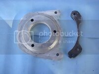
The packaging got extremely tight in a few areas, and the Wilwood items were more flexible in where I could position them. The down side was I had to fabricate the front caliper brackets and the rear bearing carrier/caliper brackets. (The rough cut rear bearing carrier and caliper bracket are shown below.)

bearingholder.jpg
 
Last edited:
Ok, a couple more. It's a really nice setup.
1) Couldn't you get the C4 diff to fit?
2) Did you use the C4 parallel 4 link setup or did you tiangulate the 2 forward links to the C3 trailing arm mounting point? I was considering a C4 rear for a different project and was wondering if the C4 rear could be mounted to a single TA point like the C3.
 
Why did you lower the tie rod inner mounts? To get the halfshafts and the rods parallel? That will severely reduce the camber curve.

Well, it's the first pass (prototype) location for the strut rods. Despite narrowing the suspension, I wanted it to look as stock and unmodified as possible. (I get a particular amusement when clueless guys at an autocross look at some of my build stuff and utter "Looks like it was just a simple bolt in modification".) The toe rods were narrowed (can't tell), and the halfshafts will be narrowed aluminum C4 units (that will also appear unchanged). The camber rods were the biggest packaging headache for me. (If you angle the stock length struts upward similar to a stock setup, the inner pivot points will be inside the differential case.) If I cut (shorten) and reweld them to fit a stock bracket, I'll always have a little concern about losing (breaking) that rod during a high speed corner. Right now that's not something I want keeping me up late at night. Another option was to assemble a custom length DOM rod/heim joint setup. That would function correctly, but it would look "out of place" with all the other aluminum suspension components. My third option was to see if a SLA setup would work in the rear, somewhat similar to a front SLA setup. Hence, my current setup. The halfshafts should describe a shorter arc than the longer strut rods, providing negative camber during (outside wheel) suspension compression. Once I've got it all running, I'll make a few skidpad measurements, and see what tweaks or direction changes I want or need to make on this.
 
Last edited:
Ok, a couple more. It's a really nice setup.
1) Couldn't you get the C4 diff to fit?
2) Did you use the C4 parallel 4 link setup or did you tiangulate the 2 forward links to the C3 trailing arm mounting point? I was considering a C4 rear for a different project and was wondering if the C4 rear could be mounted to a single TA point like the C3.

1) The C4 differential is slightly different in size and shape from the C3 units, and cutting/modifying the original body floorpan was not a palatable option for me. (I didn't want any last minute interference issues presenting themselves when I was attaching the new frame to the old body.) Also, the C3 diff is a reliable unit behind a big block, and I have several different ratio units sitting on the shelf so I can make gearing changes without having to purchase more gears or complete units.

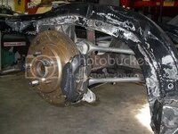
2) I used the C4 trailing links. Lighter, more adjustable, and better looking. (Here's an old picture taken during the build.)

IM000650.jpg
 
Any idea what the weight difference would be on a complete C3 (iron diff) vs C4 rear assembly?
 
Any idea what the weight difference would be on a complete C3 (iron diff) vs C4 rear assembly?

Well, it depends. Are you talking about the whole rear suspension, or just the differential section? The C3 uses either an iron or an aluminum cover and crossmember. The C3 batwing saves about 15 pounds over the iron cover and steel crossmember setup. Additionally, the C4 batwing is about ten punds lighter than the C3 batwing. And, just my guess from lifting/carrying the C3 and C4 differentials around the garage, I would guess that the C4 housing is at least 25 pounds lighter than the C3 housing. (I yield to anyone who has the opportunity to put these two items on a scale for comparison.)
Regarding the whole suspension, the C4 rear knuckle assembly and halfshafts yield another 20-22 pounds per side (40-45 pounds total) reduction.
Weighing the stock C3 parts I took off, and comparing them to the C4/aftermarket parts I put on (f&r suspension), I took about 105 pounds off the car. (Oh, and thanks to TT, I took another 6 pounds off the front end by installing a C5 master cylinder.)
 
Exactly what I wanted to know, thanks.
BTW, the project I was considering before starting the LS/vette was an L33 all aluminum 5.3L motor and narrowed C4 rear suspension in a Triumph Spitfire. There's a guy here in St Louis that's doing an LS1 in a Triumph GT6, so I'm not the only crazy one out there.
The goal was to keep the car as light as possible. Think about 300+hp in a 1300 lb car!
 
I have no iron C3 diffs lying around anymore that I can weigh, I do have several C3 and a C4 one. (all D44s)

I weighed the batwing and the C3 Dana44 once, there was a thread about it on CF. I think it was turtles weight saving thread. I'll see if I can find it and copy the info here.

Can someone weigh the C5 master cylinder and a stock one?

Let's complile a tech article with all the weights, I started it here:

http://www.vettemod.com/forum/showthread.php?p=37574
 
One other thing. The Spitfire has a similar trailing arm setup to the C3s. If a C4 rear end assembly were used, but the 2 trailing arms on each side were triangulated to a single mounting point on the frame, would that result in any problems?
 
I've got an iron diff in my shop that I can weigh if the wife doesn't catch me taking her brand new bathroom scale out to the shop. They get kind of possesive sometimes, you know. I'll post tomorrow.
 
If you think that's bad, try getting caught curing fiberglass resin with her hair drier.
I've got an iron diff in my shop that I can weigh if the wife doesn't catch me taking her brand new bathroom scale out to the shop. They get kind of possesive sometimes, you know. I'll post tomorrow.
 
The iron diff I have weighed in at 92.6 lbs. This is with both side yokes and input yoke with u-joint straps. I've already been caught using her hair drier for heat shrink on wiring. Just got "the look" with raised eyebrows.
 
Last edited:
The iron diff I have weighed in at 92.6 lbs. This is with both side yokes and input yoke with u-joint straps. I've already been caught using her hair drier for heat shrink on wiring. Just got "the look" with raised eyebrows.

Does that include the cover also?
 
Dropped the old engine back in today so I can work on the steering linkage and the brake line clearances from the m/c to the junction block. As I feared, it appears that #1 header pipe will be competing for space with the steering shaft (currently mocked up with some all-thread rod). Outside of using an old Pinto flexible steering cable to snake around the pipe (just kidding!), it looks like I'm going to have to do some tweaks on the pipe. I hate to put a clearance ding in the tube, but I may do that as a short term fix, and then later down the road I'll cut out a 10 inch section from the flange down, and re-route the pipe. The headers are ceramic coated, so that will just slow me down more than I want right now having to clean off the stuff to get to some clean metal for welding. (ps: On a side note, I'm still looking for four of the short spacers that go between the A-arm and the bolt/washer. Let me know if you have any gathering dust you'd like to sell.)

IM001063.jpg
 
Got the narrowed halfshafts back from the shop.

Picked the shafts up the other day, and stuck them in this weekend. It's a nice change from having to keep looking at the widened steel ones I used for setting things up.

IM001079.jpg

Pretty much finished with the rear suspension other than putting on the brake flexlines, and making the two outboard spring hanger bolts. The narrowed C4 spring normally attaches about four inches higher on a C4 batwing compared to my C3 batwing, so I still need to come up with something that will do the trick and not look too odd.
 
If you narrow a fiberglass C4 spring, do you just need to cut it and redrill the bolt holes?
 
If you narrow a fiberglass C4 spring, do you just need to cut it and redrill the bolt holes?

Boy, I sure hope so, cuz that's what I did. :amused: Unless you look at it close, you really can't tell it was messed with. I have a stiff Z51 spring that was my original intention to use, but after shortening this somewhat soft "test spring", the rear feels pretty firm, so I'll just leave it on for now, and see how it rides and performs. I'd like to luck out, and keep using this spring, and then I can just sell the Z51 spring sometime.
 
Well let us know if it breaks or anything. When I was looking at doing this I actually planned to epoxy some glass reinforcement around the hole. Maybe that was overkill though.
 
Got the steering linkage installed today. Used Borgeson u-joints and splined shaft. Once I got everything hooked up (u-joints phased correctly, column shaft flat clocked with the u-joint set screw), I end up with the steering wheel about 120* away from the normal center position. Once I undo the wheel and rotate it a few holes I'm hoping I'll still be able to tweak it in to the normal position.
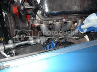
As I feared, the shaft interferes with the #1 header pipe.

IM001083.jpg

I cut the #1 pipe off, and I'm going to try to re-route it. It's not going to be easy, but if I just put a set of blockhugger headers on it (and they might not fit either after spending the money), I'd still have to weld some downpipes to the underfloor pipes, so I'm stuck doing some pipe work anyway.
 
Shame you don't live in OP here, as down the street is a exhaust magician.... I have seen that man run pipes like it was a space shuttle or something...

people say it can't be done....he just goes ahead and do it anyway....

:beer:
 
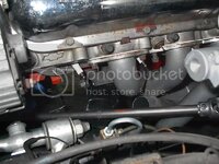
Starting to work on the header modification. As a previous post shows, the #1 pipe and the steering shaft are competing for the same real estate. I have the original tube cut out, and I made a new flange to start running a new tube. There's several restrictions on the placement of the tube (sparkplug and wire access, header bolt room, the nearby brake junction block, the upper A-arm shaft and its placement when negative camber is adjusted, and the physical size of the completed header so that it will still slide up/out between the engine and the frame), so I'm going at it slow. Here's the first tube placement. It will need to be shortened, and another elbow or two will be needed to try to get to the remaining original tube near the collector.

IM001092.jpg


I got the power steering pump plumbed to the rack today. I ordered some -6 hose and 90* ends the other day, and put them together this afternoon. (You can see the blue line near the A-arm cross shaft.)
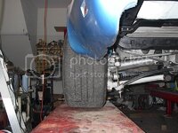
Throughout the suspension build I've been curious how much additional room the C4 suspension would provide. Just for kicks I took one of the wheels I've run on my '84, and with the aid of a VB&P 1.75" adapter, I bolted on the wheel to see what it would look like. The tire is a 315/40-16, and it looks like it might fit halfway decently.

IM001087.jpg

Down the road I might look into some 1.50" adapters to tuck the tire in a touch more. It's a long term project, but it at least looks a bit encouraging for fitment.
 
Back
Top