1958 MGA Coupe

VetteMod - Corvette Restoration, Modding & Performance Forum

Help Support VetteMod Forum:

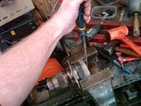
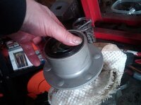
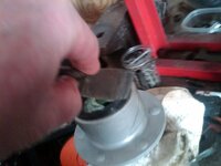
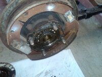
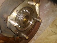
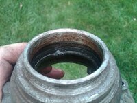
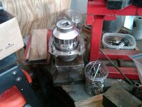
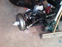
well lets pry out the hub seal

IMG02472-20131015-1550_zpsd23989e8.jpg

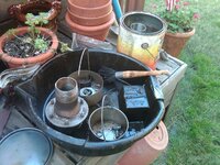
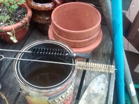
cleaning tools

IMG02480-20131015-1645_zpsc66eb402.jpg


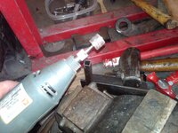
i clean up the inside diameter of the outer hub area just so there are no burrs

IMG02470-20131015-1543_zpsd1432c27.jpg

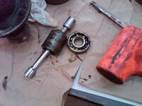
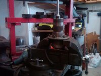
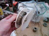
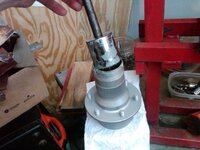
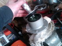
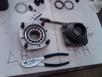
i use Barneys wau of removing the outer bearing

IMG02469-20131015-1543_zps96512e52.jpg

and then we do the inner bearing


IMG02473-20131015-1551_zpsdf4147b3.jpg

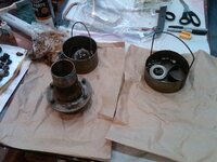
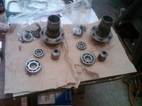
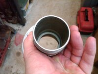
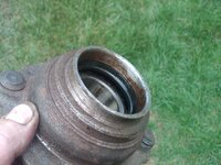
and then its clean

IMG02479-20131015-1644_zps3d353afa.jpg
 
Great work, as always......when do you think yo'll be driving ??

I am not sure I guess it depends if we sell the house and down size.....if we go down this path then the car gets mothballed until we are settled....if we dont down size then maybe next summer/fall


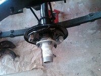
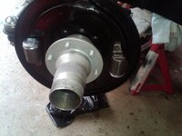
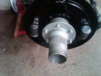
those hubs just didnt clean up like I wanted them to so i painted them with an engine enamel, i focused mainly on the areas that werent threaded.

IMG02482-20131015-2045_zps03ca04c1.jpg
 
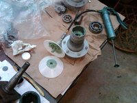
time for the very gooeey job of packing wheel bearings, i am a big fan of the green synthetic water proof grease this stuff is sticky and its a pain to clean off of tools......all the things you want in a grease.

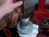
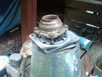
this is the inside of the hub and you can see the shoulders the bearings stop at

IMG02488-20131016-1729_zps8502caf0.jpg

IMG02489-20131016-1729_zps7ab53f8a.jpg

you can pack them by hand but i have the packing tool and it works pretty well

IMG02483-20131016-1710_zpse34ae9ea.jpg

notice no old grease coming out of the bearing thats becasue i cleaned them very well

IMG02484-20131016-1716_zpsda42e64f.jpg

IMG02485-20131016-1724_zpsdcd30b92.jpg

IMG02487-20131016-1729_zps43088c0f.jpg

IMG02486-20131016-1726_zps68970178.jpg

i measure the distance down to the bearings to make sure they are fully seated

IMG02490-20131016-1745_zpse0077a87.jpg


done!!!

IMG02491-20131016-1801_zps82c6950d.jpg
 
and as the family settled down for the night my night time prowling started........

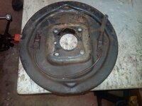
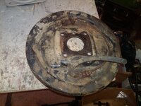
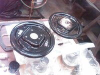
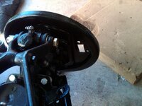
the backing plates are stamped with the side they belong to so i dont have to worry about screwing them up.


IMG02492-20131016-2115_zps722314b4.jpg

IMG02495-20131016-2116_zps790d59c8.jpg

lots of cleaning and light sanding, i am undecided if i am going to paint the inside

IMG02497-20131016-2221_zps9338ff50.jpg
 
Last edited:
As an Amazon Associate we earn from qualifying purchases. Product prices and availability are accurate as of the date/time indicated and are subject to change.
thks

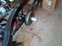
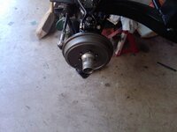
i now have a rolling chassis again....until tonight when i start on the rear hub seals

i figured out the backing plate orientation like it was when i took it off although i am not sure it makes a difference

IMG02500-20131018-1026_zpsc0949a42.jpg

IMG02501-20131018-1026_zps10408087.jpg

to install the new seals push the seal down with your hand and use the puddy knife to roll around the circumferemce of the seal this stops the rubber from bunching up...these two photos i did in one motion

IMG02506-20131018-1132_zps573c7e0b.jpg

IMG02505-20131018-1131_zps4692fdc4.jpg

seal driver for seating the seal after its in place

one big one for the out side diameter and smaller one to locate the driver
IMG02508-20131018-1147_zpsd955fed8.jpg


IMG02507-20131018-1134_zps763f4fef.jpg

IMG02503-20131018-1116_zps68d6c131.jpg

IMG02509-20131018-1150_zps04c8a478.jpg

IMG02511-20131018-1151_zps96fe2938.jpg
 
so the "5" th hole on the backing plates faces forward on the rear backing plates. i put the ice pick through the hole for reference


IMG02530-20131018-1515_zpsd6ea142d.jpg

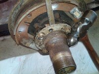
driver side slipped right off, both side were missing the screw that holds the splined hub to the bearing hub

IMG02531-20131018-1518_zps52036cc8.jpg

this side i pryed with the pry bar and light tapped on the bolts with the nuts on them and just kept rotating it unitl it popped off.

IMG02533-20131018-1531_zps8e7eb902.jpg

IMG02534-20131018-1532_zps3962e195.jpg

IMG02536-20131018-1621_zps8267ebf4.jpg

2 1/4" socket for 4whl drive vehicles $15 from advance auto. turns out my 49mm socket was a 6 sided one and did not work.

IMG02538-20131018-1624_zps182b39db.jpg


IMG02539-20131018-1629_zps39bb604a.jpg

IMG02540-20131018-1629_zps7fab9f84.jpg

time to start reading about pulling the rear hubs....
 
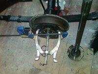
done with the reading and had a few extra minutes......i use the clamps to keep the puller locked in place or else when the bearing loosens they go falling away and you have to start all over again

IMG02544-20131018-1837_zps8fc40175.jpg

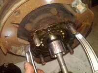
i use a shoulder socket that will allow the bearing to slip over it

IMG02542-20131018-1832_zps4efd3dc9.jpg

and they are both pulled off maybe 20 mins total

IMG02543-20131018-1835_zps96348dfd.jpg


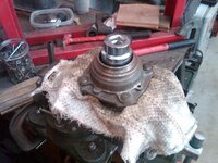
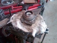
the bearing surface look nice no scoring at all and no evidence of the rear seal leaking at all
 
I have to say: from the pics I've seen you're about 15 years older than I am, you're married with kids and you're getting way more work done than me .... Lol.... That's impressive ..... Do you sleep every now and then ??????
 
I have to say: from the pics I've seen you're about 15 years older than I am, you're married with kids and you're getting way more work done than me .... Lol.... That's impressive ..... Do you sleep every now and then ??????

turned 56 yesterday whick makes be eligible to retire with 33yrs woo hoo KMA we call it. i nibble at the elephant a little bit at a time and it has a cululative effect
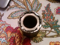

3 hrs of easy work mostly cleaning parts

IMG02570-20131019-1039_zps293db7a3.jpg

IMG02571-20131019-1040_zps8b1a7819.jpg

conpressed cylinder to take it out
IMG02573-20131019-1058_zps41799183.jpg

i think recall the brake componets are whitworth any way it was a good fit

IMG02575-20131019-1100_zpsf4343736.jpg

these are inexpensive from HF and they get used a bunch, i followed Barneys write up

IMG02577-20131019-1144_zpsd2693c17.jpg

IMG02578-20131019-1145_zpsb7db613f.jpg

IMG02576-20131019-1144_zpsf93c25ac.jpg

you can see that the the bearing and rubber seal are seperated

IMG02580-20131019-1152_zps8e367ed6.jpg

IMG02585-20131019-1156_zpsc9a51334.jpg

IMG02586-20131019-1202_zps85761d0e.jpg
IMG02587-20131019-1208_zps3da9e9aa.jpg

IMG02588-20131019-1209_zpsf220c581.jpg


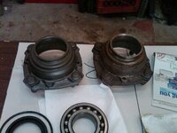
a side by side
IMG02589-20131019-1211_zpsf59a010b.jpg

just like the front hubs
IMG02591-20131019-1242_zps127d0b9b.jpg

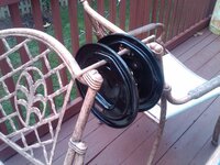
and the backing plates

IMG02594-20131019-1334_zpse1c7a119.jpg
 
Last edited:
thks

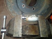
so i was thinking when i was cleaning the parts about adding four more tangs to my hub axle socket. i figure if 4 are good 8 are better

IMG02595-20131019-1629_zps02896cfe.jpg

i uses some left over angle iron about 1/8 think and cut it into 1/4" x 5/16" teeth and mig welded it in place
 
1 hour this am real easy work

test fitting the bearing/seal tool the bottom piece was a perfect fit and the bearing seals went in easier then the front ones.

IMG02596-20131020-1002_zps002829d6.jpg

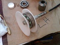
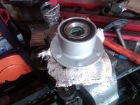
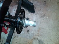
I polished the inner hub you can see where I have marked the hub if you look closely LH with a sharpie so i didnt get then confused

IMG02597-20131020-1003_zps32b7a4bc.jpg

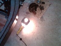
getting the hub nice and warm and the bearings got placed in the freezer after they were cleaned

IMG02598-20131020-1005_zpsb96a8721.jpg

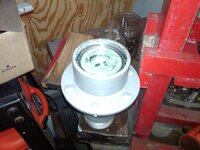
backing plate is installed and I polished the axlehub while the bearing hub is getting warm

IMG02599-20131020-1035_zps7bb80e47.jpg

well the -1* degree bearing and the light bulb hot bearing hub slipped together very easily

IMG02600-20131020-1037_zps93b09ba6.jpg

IMG02601-20131020-1056_zpsa1883a1e.jpg
 
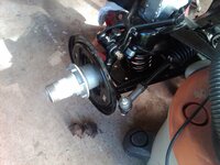
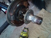
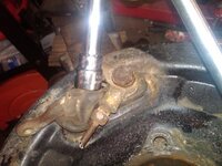
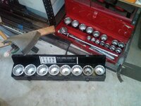
and putting them on was pretty simple I put some oil on the axle stub and the bearing race and then just used a big socket from those jumbo sets that had a greater diameter then the threaded area and some whacks with a big hammer drove it home. my torque wrench only goes to 150 ft lbs so i will see if i can use a loaner tool from an auto parts store. and then i will go back and do a final tightening and bend the locking tab over. overall it was a very succesfull weekend.

IMG02606-20131020-2012_zps83056d96.jpg

IMG02604-20131020-1857_zps109473c3.jpg
 
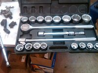
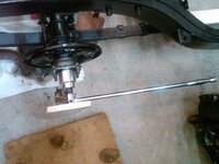
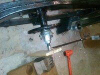
after reading Barney's website info on the real axle bearing retaining nut it became pretty clear to me that more tightness was a good thing and that there was almost no humanly way possible that I could break anything except for hurting myself. so I took this as a challenge. Eric got me thinking about leverage and I pulled out the big breaker bar. the thought here was less effort translates into more torque and a compromised tightening position would be necessary while i was to try and keep the socket on the narrow bearing axle nut while torqueing on it. I went to HF and bought the jumbo metric socket set and it had a 48mm 12 point socket and it was a good fit and it needed to be tapped on. I knew that the one I cobbled together would slip off with the big breaker bar because it was last night when i was just over 150 lbs. so my plan was from a kneeling position to lean up against a board resting on the ratchet and socket set with my hip keeping lateral pressure on them and then lean over on the breaker bar with everything else i had.

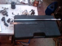
for a sense of scale
IMG02610-20131021-2214_zps51fdd4d5.jpg

IMG02609-20131021-2213_zps22657926.jpg

the set up.

IMG02608-20131021-2156_zpscae49c1a.jpg

IMG02607-20131021-2138_zpsa02c1408.jpg

well it worked I am way past 150 ft lbs not really sure how much past but i only stopped when the torque was so much that i couldnt keep the socket on the nut, so my entire upper body was leaning on the 24" breaker bar and it only slipped off after i tried to get even more of my body weight on it, it has to be over 250 ft lbs. just for fun i swung the handle around on the breaker bar and I was pulling up on it and I was picking up the frame.
 
brake time

so we take a fine wire wheel to these brake parts

IMG02617-20131025-1845_zpse95bf94f.jpg
IMG02620-20131025-1852_zps8987a779.jpg


IMG02621-20131027-1030_zpsfe2ee0b7.jpg


its like Christmas morning
IMG02622-20131027-1044_zpsfca2649f.jpg

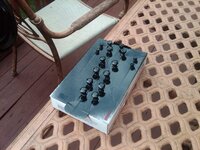
clean up the adjusters
IMG02623-20131027-1051_zpse22c8fee.jpg


while they are soaking put on some parts

IMG02624-20131027-1109_zps62be61f0.jpg

IMG02625-20131027-1110_zpsa512dcd9.jpg
IMG02628-20131027-1110_zps37a15476.jpg
IMG02629-20131027-1111_zps6c949140.jpg


clean these up and scotch brite the parts as well as i can

IMG02630-20131027-1131_zps8a9cacd4.jpg

use an awl to make sure the retaining springs will line up for the rear brakes
IMG02632-20131027-1149_zpsb95f0c01.jpg


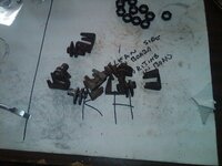
since the springs are on the back side to make the springs stay in place i ground off the sides of some bolts to push into the hole,
IMG02634-20131027-1157_zps5e7c9844.jpg

so it looks like this on the ground (note the spring is in the wrong hole it needs to be on the second holes)
IMG02635-20131027-1204_zpse3eebbcd.jpg

IMG02636-20131027-1230_zps8ac8f6c9.jpg

IMG02637-20131027-1231_zpsa18672d2.jpg

IMG02638-20131027-1232_zps23ac3a6f.jpg

IMG02643-20131027-1326_zps8f71f0d9.jpg
IMG02642-20131027-1326_zpsf6622a11.jpg

IMG02641-20131027-1325_zps1db6895c.jpg


IMG02640-20131027-1325_zps7b1bc30b.jpg
 
Last edited:
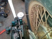
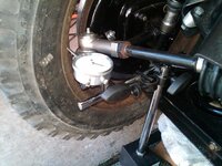
last chore for the day measuring wheel runout. move it inside or outside to avoid the weights

IMG02646-20131027-1518_zps631388a5.jpg

IMG02645-20131027-1508_zps3a114820.jpg

mine run from a low of .028 to one with .108 with 1 broken spokes and some mangled spokes. i need to digest this info some and find some specs on wheel runout
 
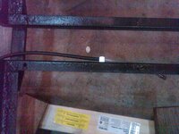
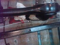
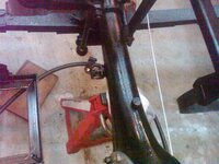
easy work tonight installing E brake cable, still need to get clevis pins and mount a anchoring bracket to the battery box. i need to find a picture of the original battery box mounting location. any body have a picture?

IMG02664-20131030-2034_zps7fbeda0e.jpg

this looked like the best orientation to me.

IMG02665-20131030-2110_zps99e02610.jpg

IMG02666-20131030-2110_zpseb747b0a.jpg

i am guessing where it is naturally going underneath the battery box frame is where the mounting tab goes

IMG02667-20131030-2111_zps4ba5cabd.jpg
 
seems to me before i do anything with plumbing, electric and cables I need to finish fitting all the rest of the chassis parts


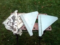
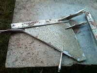
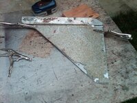
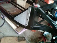
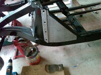
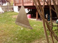
time to drill some holes in my goal post side cover plates, these are a coated steel which I am going to paint in an aluminum color becasue I like they way look that way. as you can probalby tell I am not to constrained by now they left the factory.

IMG02672-20131101-1301_zps931e73c5.jpg

IMG02673-20131101-1304_zps6787ecb6.jpg

IMG02674-20131101-1317_zpsad67d897.jpg

IMG02675-20131101-1334_zps9b0ab99f.jpg

IMG02679-20131101-1426_zps97ffde58.jpg

IMG02676-20131101-1348_zps23d1f471.jpg

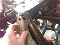
i was surprised how much the originals are "proud" of the frame here

IMG02677-20131101-1352_zpsc72d1967.jpg


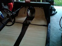
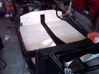
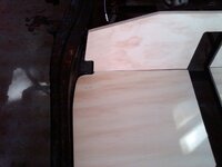
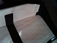
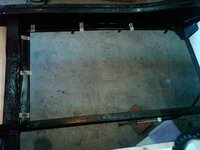
and now for the fun part test fitting the floor

IMG02680-20131101-1446_zps8eaf879c.jpg

IMG02681-20131101-1446_zpsfdf158b8.jpg

minor sanding in this area with a belt sander should be all that it needs. these are 1/2" off of ebay from Mr Dubois and they are really nice and i am very happy with them.

IMG02682-20131101-1447_zpsff877d0d.jpg

IMG02683-20131101-1447_zps10cfb17e.jpg
 
I took today off to do some out side chores and slipped 2 hrs into work on the floor boards.

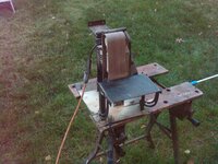
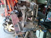
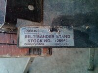
heres the belt sander mounted to a stand for removing some of the wood on the floor boards where my repair panel or welds are slightly out of shape

IMG02685-20131108-1653_zpsa4302db5.jpg

and for removing the high spots on the welds

IMG02686-20131108-1653_zpsc017f4be.jpg

you can use one of the pieces turned on its side to make sure you have the right final fit/size

IMG02688-20131108-1654_zps919356fe.jpg

inside grinding

IMG02689-20131108-1657_zps33807ebb.jpg

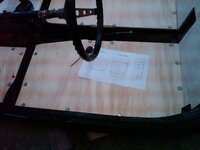
and using some of the orignal weldnut locations to start the layout process, i am using Barneys layout for the new weld nuts

IMG02690-20131108-1733_zpsd208f9c4.jpg

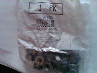
and the weld nuts for the rest of the project. i have not decided if i am going to spot weld them in or not i guess i will see the level of effort required.

IMG02692-20131108-1735_zps28d75aeb.jpg
 
this is 1/2" exterior grade 5 ply sand grade both sides and no "football" patches either

easy hour or so this afternoon, back side of the belt sander bracket, i bet you could find these on ebay

IMG02693-20131109-1409_zps9b4b0e57.jpg

IMG02695-20131109-1409_zpse1767759.jpg

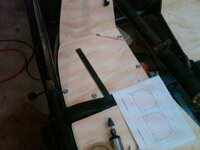
I decided to lay the holes out on the rails and then drill them from the top then put ply wood down and drill up

IMG02696-20131109-1525_zps43e014f6.jpg

IMG02697-20131109-1600_zps13d4dcbf.jpg

IMG02698-20131109-1600_zps65d02659.jpg
 
I have one of those - I use it in metal work a lot. I bought it for $5.00 at a garage sale. I spent $20 - got a Senco framing nailer, the sander, a 1000' roll of CAT 5 wiring, and something else I can't remember now.... I think I did okay :)
 
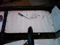
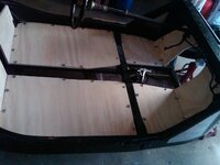
the floor boards are original design and they were 3/8 plywood originally. these are 1/2" and 5 ply. originally they were painted black.


finsihed drill the holes
IMG02699-20131110-1113_zps8ff7816b.jpg

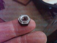
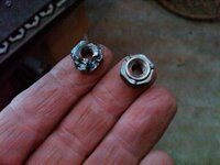
heres the weld nuts you can see it tells what size hole to drill

IMG02701-20131110-1125_zps1a7a099e.jpg

i have never done this before an i bought the spot welder for this project so lets play around some. i drill the hole and clamp the weld nut in place
IMG02702-20131110-1132_zps4514fa7f.jpg

use a grinder to remove the rough edges underneath and to give a clean weldable surface and unless your name is Brutus make a platform on the dolley for the welder to sit on

IMG02703-20131110-1138_zps755e0a39.jpg

thats what it looks like

IMG02704-20131110-1139_zpsd0ee48b1.jpg

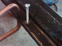
i use a long bolt to wiggle the nut.....if it breaks i do it over again.
IMG02705-20131110-1140_zps73cfb636.jpg

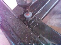
a right angle grinder with a small wheel does the trick for the grinding
IMG02706-20131110-1143_zpsfd717aa1.jpg

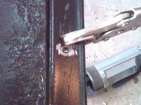
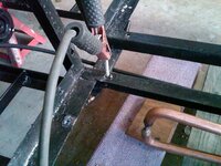
the spot welder tongs will not fit inside the heavy frame channel so we will mig it up

IMG02707-20131110-1230_zpsa1351668.jpg

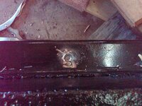
these just say for me to mig weld the hole's

IMG02708-20131110-1444_zps3b08f6ae.jpg
IMG02709-20131110-1444_zps872d5c63.jpg

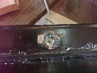
welded and ground down

IMG02710-20131110-1501_zps7e6c2bdb.jpg

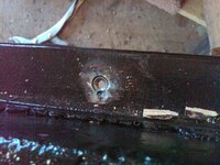
and if you screw it up this is what it looks like

IMG02711-20131110-1514_zps0c7028bf.jpg

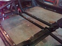
done with the main floor boards. i need to think about how i can make a more uniform clamping jig just for the spot welder.

IMG02712-20131110-1550_zps93846e48.jpg
 
i saw the new string ray yesterday drving by it was interesting
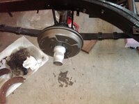
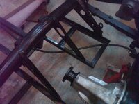
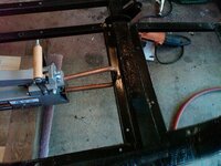
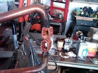
so i went to bed last night thinking of how to make a clamping jig for the spot welder....for those big copper jaws.....

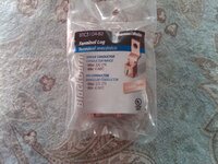
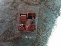
so where is there copper in misc sizes....the electrical dept of HD

IMG02714-20131111-0915_zps4e69f89d.jpg

IMG02715-20131111-0916_zps5498c0f2.jpg

IMG02716-20131111-1129_zps0af91e0c.jpg

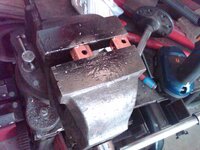
lets make some holes on the flat sides

IMG02717-20131111-1132_zps094192e7.jpg

IMG02718-20131111-1133_zpsf5de979a.jpg

you get the idea

IMG02719-20131111-1146_zpsfeb443c3.jpg
IMG02720-20131111-1230_zps7a45353b.jpg

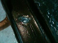
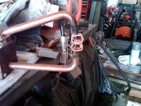
and oh yeah those copper pieces get hot so have a tub of water to drop them in. didnt take very long you just have to use your fingers with the hot tongs for placing the jaws so its mostly waiting for the jaws to cool down. my bottom jaw was actually in the hole of the weld nut. you place that first. it would have been easier with a third hand.
 
Back
Top