Six Link Rear Suspension

VetteMod - Corvette Restoration, Modding & Performance Forum

Help Support VetteMod Forum:

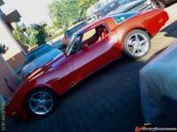
The system is designed by me for my 79 C3..... and everything clear w/o problems all the fiberglass!

The system requires only some minor welding under the trailing arm bosses...... and you will have the possibility to go back to the original system.
 
The system is designed by me for my 79 C3..... and everything clear w/o problems all the fiberglass!

The system requires only some minor welding under the trailing arm bosses...... and you will have the possibility to go back to the original system.


Thanks Pier Paolo
No problem welding the frame or cutting the fiberglass, I was just curious
Again, like TT said earlier we should be on our knees thanking you for this
LOL
(did I write this right??? nobody pissed??) ;)

Tell me Pier Paolo,
how does the car handles differently than with the old suspension?
And what size sway or anti roll bar did you use?
 
Last edited:
You can't use his sway bar size since he uses coil overs, if you run a leaf you have to run a thinner sway bar, with a dual mount spring even thinner or none at all.

The suspensuon is vastly superior to stock especially when it comes to toe control. Another nice feaure is the upper camber struts, taking the halfshafts out of the geometry and using them just as driveshafts, no more sloppy stub axle/c-clip woes messing up camber control.
 
Right Marck!

At the front I run a tubular 42 x 2mm. sway bar and coilovers.
At the rear I run very short coilovers (11.3") and quite stiff springs (550 lbs).... so I really don't need sway bar at all.

The car is a lot more predictable than before (no jacking at all) and the bump toe control is very good (first step towards consistency).
Is quite flat on the corners (some roll is not bad for performance..... it makes the car less nervouse and more "talking" close to the grip limits).

Take in consideration that I have C6 wheel and tires.... which is a great thing for performances!!

The funniest thing is that you really can adjust the way the car will handle...... neutral, over or under-steering.... according with your feeling!
 
As an Amazon Associate we earn from qualifying purchases. Product prices and availability are accurate as of the date/time indicated and are subject to change.
Take in consideration that I have C6 wheel and tires.... which is a great thing for performances!!

What size are the wheels and tires, backspace? did you use spacers? I see you used original calipers and rotors so no problems with clearance.

Also would there be a big difference if the bushing on the diff crossmember are not replaced by alu disks?
 
Last edited:
Actually I have front and rear Wilwood with 13" rotors ...... is not easy to see it in this picture.... but is the only I have!

thum_1449c16bce7f121.jpg

Anyway, in order to install C6 wheels you need 3" spacers at front and rear.
The tires are the same than C6 (245/40-R18 and 285/35-R19)
 
Last edited:
The system is designed by me for my 79 C3..... and everything clear w/o problems all the fiberglass!

The system requires only some minor welding under the trailing arm bosses...... and you will have the possibility to go back to the original system.


Thanks Pier Paolo
No problem welding the frame or cutting the fiberglass, I was just curious
Again, like TT said earlier we should be on our knees thanking you for this
LOL
(did I write this right??? nobody pissed??) ;)

Tell me Pier Paolo,
how does the car handles differently than with the old suspension?
And what size sway or anti roll bar did you use?

This is really interesting and would like to reproduce it, is there a DIY guide?

Also, is it possible to use C4 knuckles(sp) instead of C3?
 
In some place here (ask to Marck) there are the cutting plans for the parts you need to reproduce my setup.

Like I sed before my old PC is death..... and I no more have the drawings......
Anyway some friend here allready received the drawings from me some time a go.... so you can have it!

Basically you need to buy 20 rodends of 5/8" and the related rods.
I have used wath was avalaible in the VBandP catalog....
4 of the longer rods for the C4 setup for the front links,
2 smart-strut kit (8 rods)
2 shorter rods for the upper links

.... a lot of 1/2" bolts and nuts..... a lot of spacers..... and nearly 100mt of wire for my MIG welder!
 
In some place here (ask to Marck) there are the cutting plans for the parts you need to reproduce my setup.

Like I sed before my old PC is death..... and I no more have the drawings......
Anyway some friend here allready received the drawings from me some time a go.... so you can have it!

Basically you need to buy 20 rodends of 5/8" and the related rods.
I have used wath was avalaible in the VBandP catalog....
4 of the longer rods for the C4 setup for the front links,
2 smart-strut kit (8 rods)
2 shorter rods for the upper links

.... a lot of 1/2" bolts and nuts..... a lot of spacers..... and nearly 100mt of wire for my MIG welder!

Your plans are in the download section.

http://www.vettemod.com/forum/downloads.php?do=file&id=61
 
In some place here (ask to Marck) there are the cutting plans for the parts you need to reproduce my setup.

Like I sed before my old PC is death..... and I no more have the drawings......
Anyway some friend here allready received the drawings from me some time a go.... so you can have it!

Basically you need to buy 20 rodends of 5/8" and the related rods.
I have used wath was avalaible in the VBandP catalog....
4 of the longer rods for the C4 setup for the front links,
2 smart-strut kit (8 rods)
2 shorter rods for the upper links

.... a lot of 1/2" bolts and nuts..... a lot of spacers..... and nearly 100mt of wire for my MIG welder!

Your plans are in the download section.

http://www.vettemod.com/forum/downloads.php?do=file&id=61


Ok, I have the blueprint now.
The parts are cut in 1/4" steel plate, but it is mecessary to use that or 1/8" will be ok?. The standard TA wall thickness is less that 1/8"

Thanks
 
The files you downloaded are not the latest revision, they are not complete. NOT all parts are there. I have to upload the correct ones, had a nasty rootkit virus a week ago and still have to recover the old files....
 
I'm back!!!!!!!!!!!!!!!!

I had a provider problem (changed house)..... but finally I have a stable connection!

Sorry for not answering to the mails..... can I help now Stingxray?
 
Trailing Rods /strut 5/8 Heim length

Welcome back Pier Paolo:

I thought you might have met with an untimely demise ....:gurney:. Anyway glad your back.
When you get the chance............... could you measure all your adjustment rod lengths for you 6 link ? Just the rod length............ without the heim joint's or locking nuts. I'm looking to have a set of 10 LH & RH threaded rods made up in thick wall aluminum ... sure would make life easier.

Heim Joint and adjustment rod supplier>>>>>>>>>>>.

http://www.pitstopusa.com/Categories.aspx?ID=3381

Thanks Again Respectfully GRA3 :o
 
Starting to cut parts and Ohh oooo... Material thickness

This question is meant for Pier-Paolo , but please .....anyone can chime in. I had purchased plate stainless material and took to my cousins shop and was ready to be cut. Unfortunately we found out late it's thinner than the plans require.(don't trust anyone...measure it your self). Ok So plans call for 8 MM for outer 2 brackets and cross bar and 6 MM for the rest. As it turns out.... My sheets measure , 1/4 (6.35 MM) and 3/16 (4.75mm) . My delema is can I substitute the thinner 2 or should I double up as (Pablo did) the 4.75 mm for the outer bracket = 9.5mm ? That's the critical load bearing plate that the bearing hub bolts to. Is this over kill ? I'm not sure what the factory trailing arm thickness is? The projects on hold now :huh: Input.....
Thanks Grant :clobbered:
 
Last edited:
The configuration is a little different but the thickness of my offset arms is 1/4 inch. The material thickness of the stock arms is much less.
 
Sorry but I think that Grant is talking about the thikness of the TA in the area where the hub is bolted.
In this area the stock TA is some 3/8" thik.
For my opinion it is a good move to build this section with two layers of 3/16"..... its an area with lot of stress!
 
Progress..........

Thanks Pier & BBshark :
I'll have to do some shuffling but think I have enough material. One more thing.............. The later version of Pier's 6 link cad files has..... what looks like an extra cross bracket (w/ holes). Where does it go and what thickness should it be? Thanks Grant :cool:
 
Me Too...

I am in the process of having all of the material cut out of stainless for the 6-link. I will post pics in the future. I will be running an 80-82 aluminum batwing mounted to my iron 72 pumpkin (4.11 gear). Adjustible fiberglass (VBP) springs will also be mounted.
 
I am in the process of having all of the material cut out of stainless for the 6-link. I will post pics in the future. I will be running an 80-82 aluminum batwing mounted to my iron 72 pumpkin (4.11 gear). Adjustible fiberglass (VBP) springs will also be mounted.


New member...

Welcome to the motley crew of the Flying Dutchmen....

:D
 
-B file corrupted

Hi Guys,

I downloaded the files but the ultra-link-new-6mm-B.dxf file was corrupt. Does anybody have a full set?

TT are the files on the download link the latest version or is an update still in the works?

Thanx

Grampy
 
Tested the zip file, works fine. All files open just fine too. If still not working, let me know. It is the latest rev. I have.
 
"These are the cutting patterns to build your own Stroker-427 Design 6 link rear suspension.

These are not the final designs, some parts are missing. Will upload new files later (hopefully soon)
"

That sums it up! I'm gonna cut some card templates to see what fits and what doesn't.


NOTE: This set does not have the outlines - but the internal cuts/drill locations:


NOTE: This is what I believe those should look like when cut:


I will hopefully cut some card stock for fitment checks this weekend. I'll post followup pics after that, so we'll have an idea of whats - what.
(BTW - many thanks to Twin Turbo for hosting and posting!)

ANYBODY GOT PLANS FOR RACK AND PINION GEAR MOUNTS????

Cheers - Jim

NOTE __ I'll change the colors on the grey bolcks a little later so be easier to read -- but gotta go now :D
 
Last edited:
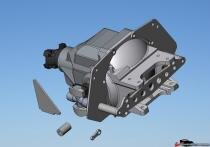
Well, The part I'm most interested in - The diff mounts are not there.

thum_12694aad7138106ef.jpg


There are 2 mini-batwings, but not the 2 plates for attaching to the diff.
If you want to do the new hub mounts and the mounts to replace the rear Trailing arms, it seems most (all?) are there. Oh Well, may have saved some card stock - but I may tackle the diff mount setup.

Cheers - Jim
 
Back
Top