C4 suspension LCA mounting method change?

VetteMod - Corvette Restoration, Modding & Performance Forum

Help Support VetteMod Forum:

69427

The Artist formerly known as Turbo84
Joined
Mar 30, 2008
Messages
3,080
Reaction score
42
City & State/Province
Clinging to my guns and religion in KCMO.
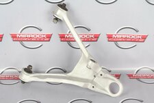
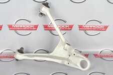
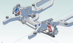
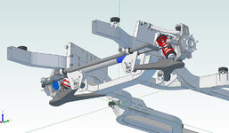
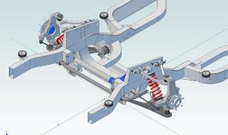
I've had my (lighter replacement) aluminum LCA crossmember 90% finished for quite some time, but I'm not comfortable with the regular method of attaching the lower control arms (clamping/bending the crossmember tabs/flanges to prevent the steel bushing from rotating around the attachment bolts). I'm considering trying to fabricate a shaft piece that looks like what the C3 LCAs use, that then bolts to the front crossmember (or modify a C3 shaft, as the dimensions are somewhat in the same ballpark). This would allow me to just bolt the LCA shafts to the crossmember, with no tabs or bending stress involved. (I could also shim the shaft mounts outward if I wanted to change the camber or trackwidth.)

Just kicking around ideas at the moment. Please feel free to comment about this.
 
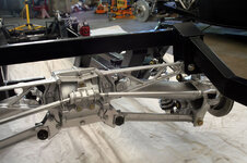
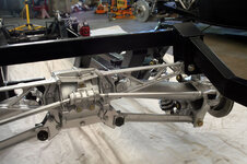
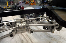
Had to refresh my memory of the C4 rear suspension. I think this is the stock LCA setup right?

008.jpg
 
Had to refresh my memory of the C4 rear suspension. I think this is the stock LCA setup right?
...................

Yeah, that's a C4 rear suspension, but I'm working on the front suspension LCA (A-arms). I'm trying to come up with an alternate method of bolting in the lower control arms without having to squish any parts of the aluminum crossmember I welded up.
 
I don't know where I came up with rear suspension:huh2:

Now I get it. Could you shim/spacer the bolts so they don't bend the aluminum tabs? The C3 part is a chunk.

s-l640.jpg
 
95c3533dc377a0de73e39800fba22c82.jpg
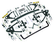
There is a lot of stuff in that image - but I'm looking at the lower wishbone. Note how it mounts to the C3 front cross-member (K-bar/A-bar- I forget). That cross-member attaches (bolted) to 2 tabs on the C3 member.
Could something like that be in the works? It's the heavy - dog bones that bolt up.
Seems simple enough with your welding skill to fab that piece up. (No challenge intended.)
You could use heim/rod ends on either the outboard and/or inboard ends to give heaps of adjustment.

Cheers - Jim
 
As an Amazon Associate we earn from qualifying purchases. Product prices and availability are accurate as of the date/time indicated and are subject to change.
..... It's the heavy - dog bones that bolt up......

Cheers - Jim

A cross shaft is going to be more than a few OZ’s... I vote some poly bushings to limit the squish. Can I assume you don’t want the tabs to squish for metal fatigue reasons?
 
..... It's the heavy - dog bones that bolt up......

Cheers - Jim

A cross shaft is going to be more than a few OZ’s... I vote some poly bushings to limit the squish. Can I assume you don’t want the tabs to squish for metal fatigue reasons?

Correct. The C5-C7 LCA tabs on the cradle are part of the crossmember casting. Any tabs I put in my crossmember would have to be welded in (most likely). I'm a double E, not an ME, and I occasionally run into scenarios that are out of my comfort zone.

I can't disagree that the cross shaft would be an inefficient use of additional weight.
 
I don't know where I came up with rear suspension:huh2:

Now I get it. Could you shim/spacer the bolts so they don't bend the aluminum tabs? The C3 part is a chunk.

s-l640.jpg

I've entertained that. The issue, as I understand it, is that the inner bushing steel tube needs to be compressed lengthwise to lock it to the tabs, so that the tube doesn't rotate relative to the through bolt during suspension travel. I keep envisioning these shim spacers in the same light/function as the rear axle preload shims on each side of the differential carrier side bearings. Perhaps if I collect a pile of assorted thickness 1/2" washers, I could use one thickness when welding the tabs in solidly, and then use (ie: pound in) a couple slightly thicker washers between the tabs and the bushing tubes. I think I'll measure a bunch of washers tomorrow to see if I can find a range of thicknesses.

I suspect you're correct that the C3 cross shaft is a chunk of weight.
 
Been a while so I won't run any numbers - but what about 2 separate sections with a web between? Think "I-Beam". Less weight - all those spars in aircraft etc are basically similar "displaced" members.

Cheers - Jim
Rather than add a post - I'll edit...
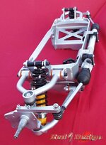
This looks like an interesting approach:
092fe5c215d5b448c168461854954a3a.jpg
and:
Chassis_Assembly2.jpg
Replicate for the LCA - You wouldn't need a full dogbone - just some bearing points. Remember that the LCA takes at least 60% of the load and the UCA 40 or less!
For more images:
http://www.quarkdog.com/El_Camino/Pages/Sub_Pages/Front-Suspension.html
 
Last edited:
Been a while so I won't run any numbers - but what about 2 separate sections with a web between? Think "I-Beam". Less weight - all those spars in aircraft etc are basically similar "displaced" members.

Cheers - Jim
Rather than add a post - I'll edit...
This looks like an interesting approach:
092fe5c215d5b448c168461854954a3a.jpg
and:
..............
Replicate for the LCA - You wouldn't need a full dogbone - just some bearing points. Remember that the LCA takes at least 60% of the load and the UCA 40 or less!
.....................

Yeah, I have been wanting to copy the UCA attachment method above for the LCAs, but I have never seen it done on any cars. Corvettes don't do it so that they can use the LCA eccentrics to adjust the camber. I adjust camber via the UCAs, so I'm not constrained there. The thought/possibility that I'm neglecting a key issue that makes this (UCA) mount design unwise for use in the LCAs was why I was entertaining the dogbone (C3 design) mount for my setup. This worry may be valid, or nonsense. I don't know which.

I don't have a C5-C7 UCA to look at here (all my stuff is C3 and C4). Is the UCA rubber portion of the bushing "glued/cemented/splined" to the anchor pin so that there's no relative rotation between the materials? From any pictures I've seen, there's not an obvious steel tube (that needs compressing) between the rubber and the anchor pin like on my C4 control arm bushings.
 
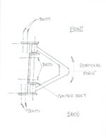
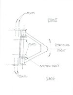
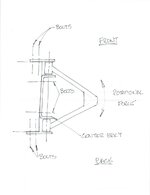
I'm thinking that the forces acting on the A-arm are greatest under braking (which produces a rotational force) that tries to push the rear mount towards the center of the car and the front mount away. If you were to bolt simple plates onto the outside of the arm mounts, you could sim those plates through the bolted connection and shear forces axial to the plates would be countered by the bolts.

In between the A-arm pivots would be U bent bracket that would be bolted (or welded) but would not be a welded "tab" with a stress concentration at the bend.

This is all fabricated stuff with bolted connections which may be easier to make and with some adjustability.

4602d9a5541298.jpg
 
I'm thinking that the forces acting on the A-arm are greatest under braking (which produces a rotational force) that tries to push the rear mount towards the center of the car and the front mount away. If you were to bolt simple plates onto the outside of the arm mounts, you could sim those plates through the bolted connection and shear forces axial to the plates would be countered by the bolts.

In between the A-arm pivots would be U bent bracket that would be bolted (or welded) but would not be a welded "tab" with a stress concentration at the bend.

This is all fabricated stuff with bolted connections which may be easier to make and with some adjustability.

4602d9a5541298.jpg

Yeah, I like that. I could probably do that with only minor modifications to the present configuration of the crossmember. :thumbs:
 
I'm thinking that the forces acting on the A-arm are greatest under braking (which produces a rotational force) that tries to push the rear mount towards the center of the car and the front mount away. If you were to bolt simple plates onto the outside of the arm mounts, you could sim those plates through the bolted connection and shear forces axial to the plates would be countered by the bolts.

In between the A-arm pivots would be U bent bracket that would be bolted (or welded) but would not be a welded "tab" with a stress concentration at the bend.

This is all fabricated stuff with bolted connections which may be easier to make and with some adjustability.

4602d9a5541298.jpg

Well, I'm getting my winter project list written up, and getting the front aluminum crossmember finished is high on the list. (It's 8# lighter than the current steel crossmember.) I've kicked around several ideas, and none have seemed as feasible (and user friendly if I have to modify the mounts for suspension geometry changes) as what you have in your drawing. I'm going to go with your suggestion. Thanks, Larry. :thumbs:
 
I'm sure you'll consider (perhaps) remounting the steering rack in the design?

Just asking as I'm getting ready (as always) to once again relocate mine - back to rear steer as there is so much more room with the engine aft.

Would like to see your plans once you have something sketched out if you'd be willing to share.


added: Just found this nice looking modular approach. Could get all the key points at once - stiffness, placement of LCA/UCA, steering rack shock options...

273cbccbaf7ca58191e86859c9b0fd66.jpg
Cheers - Jim
 
Last edited:
I'm thinking that the forces acting on the A-arm are greatest under braking (which produces a rotational force) that tries to push the rear mount towards the center of the car and the front mount away. If you were to bolt simple plates onto the outside of the arm mounts, you could sim those plates through the bolted connection and shear forces axial to the plates would be countered by the bolts.

In between the A-arm pivots would be U bent bracket that would be bolted (or welded) but would not be a welded "tab" with a stress concentration at the bend.

This is all fabricated stuff with bolted connections which may be easier to make and with some adjustability.

Well, I'm getting my winter project list written up, and getting the front aluminum crossmember finished is high on the list. (It's 8# lighter than the current steel crossmember.) I've kicked around several ideas, and none have seemed as feasible (and user friendly if I have to modify the mounts for suspension geometry changes) as what you have in your drawing. I'm going to go with your suggestion. Thanks, Larry. :thumbs:

Glad I could help. I wish I could plan out my projects. I have be re-doing a lot of stuff lately :suicide:
 
I'm sure you'll consider (perhaps) remounting the steering rack in the design?

Just asking as I'm getting ready (as always) to once again relocate mine - back to rear steer as there is so much more room with the engine aft.

Would like to see your plans once you have something sketched out if you'd be willing to share.


..............................
Cheers - Jim

I don't know if I have any pictures (I'll look), but I'm just reusing/transferring the rack mounting bracket from the current steel crossmember to the aluminum crossmember (whenever I get the darn thing completed). Most every suspension and steering mounts on my car are bolt-on pieces, which allow me to remove and modify/replace these pieces when I want to tweak the suspension (or correct a mistake). The rack bolts to an aluminum bracket (27 oz), and this bracket then bolts to the LCA crossmember. This bolt-on option came in handy a few years ago when I wanted to move the rack placement to change the Ackermann level.
 
I'm thinking that the forces acting on the A-arm are greatest under braking (which produces a rotational force) that tries to push the rear mount towards the center of the car and the front mount away. If you were to bolt simple plates onto the outside of the arm mounts, you could sim those plates through the bolted connection and shear forces axial to the plates would be countered by the bolts.

In between the A-arm pivots would be U bent bracket that would be bolted (or welded) but would not be a welded "tab" with a stress concentration at the bend.

This is all fabricated stuff with bolted connections which may be easier to make and with some adjustability.

Well, I'm getting my winter project list written up, and getting the front aluminum crossmember finished is high on the list. (It's 8# lighter than the current steel crossmember.) I've kicked around several ideas, and none have seemed as feasible (and user friendly if I have to modify the mounts for suspension geometry changes) as what you have in your drawing. I'm going to go with your suggestion. Thanks, Larry. :thumbs:

Glad I could help. I wish I could plan out my projects. I have be re-doing a lot of stuff lately :suicide:

I can relate to the bolded above. BTDT. It used to bother me, but several years ago there was a Corvette guy (NorvalWilhelm/Strider) that used to do a bunch of fabrication stuff, and I was always envious as I had to too often redo my stuff to get it to look decent. I complimented him about that, and he was honest enough to say that he frequently redoes his stuff until he's happy with both the operation and appearance of it. I thought, wow, even some of the experienced guys aren't always happy with the results of their first design, and end up reworking things. I've gotten better at my welding and fabricating over the years, but I still redo my stuff on occasion, and I cope better with it than I used to.
 
Shortening/welding camber struts?

Had to refresh my memory of the C4 rear suspension. I think this is the stock LCA setup right?

008.jpg

Borrowing your picture, and hijacking my own thread here. I've been pondering shortening the strut rods to reduce the camber gain. My main concern at the moment is if it's an unwise move to modify an aluminum suspension component, and just go with steel tubing and Heim joints. I might entertain installing a Heim setup to dial in the handling, but that one non-engineer molecule in my brain likes the stock look of the aluminum struts. FWIW, I cut and narrowed the outer batwing area on my setup to fit inside the C3 frame with no problems seen, or any sleep lost, but active suspension components cause me a little more discomfort.

So, any comments/advice on the safety aspects of rewelding and gusseting the stock aluminum struts? Or should I just hope that the tube/Heim setup is lighter, and let the weight issue trump the appearance issue?

Thanks for any and all input.
 
The rack bolts to an aluminum bracket (27 oz), and this bracket then bolts to the LCA crossmember. This bolt-on option came in handy a few years ago when I wanted to move the rack placement to change the Ackermann level.

As you have time, that would be a great layout/picture to see/copy.

Thanks - and Happy New Year! :trumpet:

Cheers - Jim
 
Had to refresh my memory of the C4 rear suspension. I think this is the stock LCA setup right?

008.jpg

Borrowing your picture, and hijacking my own thread here. I've been pondering shortening the strut rods to reduce the camber gain. My main concern at the moment is if it's an unwise move to modify an aluminum suspension component, and just go with steel tubing and Heim joints. I might entertain installing a Heim setup to dial in the handling, but that one non-engineer molecule in my brain likes the stock look of the aluminum struts. FWIW, I cut and narrowed the outer batwing area on my setup to fit inside the C3 frame with no problems seen, or any sleep lost, but active suspension components cause me a little more discomfort.

So, any comments/advice on the safety aspects of rewelding and gusseting the stock aluminum struts? Or should I just hope that the tube/Heim setup is lighter, and let the weight issue trump the appearance issue?

Thanks for any and all input.

I'm guessing these are adjusted with cams (like a C3)? I'm no expert on welding but aren't those forgings? Any issue with welding forgings? OK, I think I have reached my allotment of questions.

Oh, one more, what is the benefit of reducing camber gain?
 
Oh, one more, what is the benefit of reducing camber gain?
Just a guess:
Make up for very soft springs?
Or, is there a steering issue?​
What is the current gain? How much do you want to reduce it?
Inquiring minds want to know.
Cheers - Jim
 
.........................
I'm guessing these are adjusted with cams (like a C3)? I'm no expert on welding but aren't those forgings? Any issue with welding forgings? OK, I think I have reached my allotment of questions.

Oh, one more, what is the benefit of reducing camber gain?

First two questions, I am unqualified to answer.

Third question: If there's too much camber gain, there will be excess wear on the inner portions of the tire/tread. I currently have too much camber gain.

In addition to reducing tire wear, the reduction of (excess) camber gain should help cornering capability and stability. Also, during low speed acceleration or high speed deceleration, the reduction of excess camber gain should keep the tread flatter, resulting in better traction for both acceleration and rear wheel braking.

When I put this narrowed C4 suspension in years ago, I kept the strut rods the stock length (because of cutting/welding concerns), and positioned the inner pivot points such that the rear suspension would act like an SLA (Short/Long Arm) front suspension. It does that, but the fixed placement of the halfshafts does not allow a lot of geometry options. So, I need to shorten the camber strut rod.
 
Oh, one more, what is the benefit of reducing camber gain?
Just a guess:
Make up for very soft springs?
Or, is there a steering issue?
What is the current gain? How much do you want to reduce it?
Inquiring minds want to know.
Cheers - Jim

I've bounced back and forth between the two '84 rear springs, neither of them known for being soft, but I haven't been able to package a rear sway bar with this suspension/frame combo, so all my rear roll stiffness is coming from the spring. Not ideal.

I've also gotten rid of most of the rear roll (under)steer built into C4 suspensions, so I want to make sure that I'm "maximizing" what rear traction I can get with the limited width tires that fit under my stock fenders.

I don't have any numbers on the camber gain. I just have observed that my tires are wearing unacceptably, and that it's too often a bit too "exciting" keeping the rear end going straight under hard braking.
 
“ So, any comments/advice on the safety aspects of rewelding and gusseting the stock aluminum struts? Or should I just hope that the tube/Heim setup is lighter, and let the weight issue trump the appearance issue?”

You can buy chrome moly tubing kits with the heims, threaded inserts, and tubing. I’ve bought a few from S&W which were sold as engine limiter kits.

Or, buy some 6061 and machine some new ones.

After my experience welding cast aluminum, I’d say bad idea on safety related part. But, you’ve had good luck on the batwing.

Just a suggestion.
 
Back
Top