
You are using an out of date browser. It may not display this or other websites correctly.
You should upgrade or use an alternative browser.
You should upgrade or use an alternative browser.
Internal Body Aerodynamics
- Thread starter vette427sbc
- Start date

Help Support VetteMod Forum:

A one off custom made Ferarri? I'll bet that cost some big money.
Beautiful car!
Beautiful car!

rtj
Well-known member
- Joined
- Nov 5, 2011
- Messages
- 3,598
- Reaction score
- 211
A one off custom made Ferarri? I'll bet that cost some big money.
Beautiful car!
Yeah, when the Ferrari employee thanked the buyer for the opportunity to design and build a car, I figured it must have been a blank check ( i.e., no budget worries).

Pretty cool how YouTube AI feeds up new videos, this one was only up 2 days.
Seems like if you want to keep abreast with automotive aero, you have to watch the really high end stuff.
Last edited:


![Pampers Sensitive Baby Wipes, Clinically Proven, Fragrance Free, Unscented, Water Based, Hypoallergenic, Multi-Use, Hand Wipes 336 Wipes Total (6X Flip-Top Packs) [Packaging May Vary]](https://m.media-amazon.com/images/I/41KLBHu9CAL._SL500_.jpg)






As an Amazon Associate we earn from qualifying purchases. Product prices and availability are accurate as of the date/time indicated and are subject to change.

COLE SWEAT
Well-known member
- Joined
- May 8, 2013
- Messages
- 142
- Reaction score
- 7
On the 68, 69 years they have the 4 grills behind the front wheels.
1 of the grills is blocked off, if it was opened up to the wheel well could it pull the air out of the wheel well?
1 of the grills is blocked off, if it was opened up to the wheel well could it pull the air out of the wheel well?

phantomjock
Well-known member
That is a Great Question. I had to go ask the Oracle:

Then, since my car is so torn up, a little digging on the chassis details:
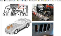
The challenge to getting the air out of the wheel well will be the inner fender well. With some modifications, yes, I bet it would help. And, you could eliminate using the “over fender” louvers. [There is an additional advantage to the louvers as they dump air into a low pressure zone…]
But, you could with a small-ish, cheap fan – get air from the engine compartment quite easily. I bet there might be bigger pay-off to that with under-hood temperatures, including an oil cooler, and a major source of internal drag!
It’s all a trade-off. Best of luck. Thanks for getting me thinking!
Cheers - Jim
PS - Found this over at Pro-Touring [checking out front suspension builds] It clearly shows where you'd have to mod to work the wheel well through the "gills." I bet it could be very useful with a duct from the existing well to the gills. Enjoy!
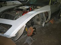
Then, since my car is so torn up, a little digging on the chassis details:
The challenge to getting the air out of the wheel well will be the inner fender well. With some modifications, yes, I bet it would help. And, you could eliminate using the “over fender” louvers. [There is an additional advantage to the louvers as they dump air into a low pressure zone…]
But, you could with a small-ish, cheap fan – get air from the engine compartment quite easily. I bet there might be bigger pay-off to that with under-hood temperatures, including an oil cooler, and a major source of internal drag!
It’s all a trade-off. Best of luck. Thanks for getting me thinking!
Cheers - Jim
PS - Found this over at Pro-Touring [checking out front suspension builds] It clearly shows where you'd have to mod to work the wheel well through the "gills." I bet it could be very useful with a duct from the existing well to the gills. Enjoy!
Last edited:

vette427sbc
Well-known member
On the 68, 69 years they have the 4 grills behind the front wheels.
1 of the grills is blocked off, if it was opened up to the wheel well could it pull the air out of the wheel well?
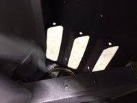
Not easily... the other gill (if opened) would evacuate air from the cowl. The other thing is that the body mount is in the way. I have already clearanced mine about as much as I feel comfortable.
Very rough mock up of my cooler:
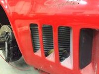

Hard to see, but I took a fair amount of the triangulation out of the body mount to allow a smoother duct
vette427sbc
Well-known member
It will be interesting to see if it needs an exhaust fan. Nice work on the install.
Thanks! It will be sealed off and fed by the wheel well... Hopefully no fans required

OZgreen69
Well-known member
What I have found with those gills is, after a race they are covered in brake dust. So me think that I do not have much air flow exiting the engine bay to push that dust out. And the steel plates at the bottom of the guards are there.
Confused....
I remember of a race cars engineer I was working with, who always asked me not to clean anything post race, for him to have a good look at how dirty the car was in certain locations . Must be a sign ?
Confused....
I remember of a race cars engineer I was working with, who always asked me not to clean anything post race, for him to have a good look at how dirty the car was in certain locations . Must be a sign ?
Last edited:

69427
The Artist formerly known as Turbo84
- Joined
- Mar 30, 2008
- Messages
- 3,080
- Reaction score
- 42
- City & State/Province
- Clinging to my guns and religion in KCMO.
What I have found with those gills is, after a race they are covered in brake dust. So me think that I do not have much air flow exiting the engine bay to push that dust out. And the steel plates at the bottom of the guards are there.
Confused.... I'm confused about the steel plates and guards you're referring to.
I remember of a race cars engineer I was working with, who always asked me not to clean anything post race, for him to have a good look at how dirty the car was in certain locations . Must be a sign ?
His request to not clean/tamper with the car makes sense. :thumbs:
vette427sbc
Well-known member
There are metal plates that bolt to the bottom of the fenders and tie them to the bottom of the wheel well... mine (stock?) were steel. Easily replicated in aluminum :amused:
69427
The Artist formerly known as Turbo84
- Joined
- Mar 30, 2008
- Messages
- 3,080
- Reaction score
- 42
- City & State/Province
- Clinging to my guns and religion in KCMO.
There are metal plates that bolt to the bottom of the fenders and tie them to the bottom of the wheel well... mine (stock?) were steel. Easily replicated in aluminum :amused:
I'll have to take a look. :thumbs:
OZgreen69
Well-known member
:thumbs: Yes those one !
69427
The Artist formerly known as Turbo84
- Joined
- Mar 30, 2008
- Messages
- 3,080
- Reaction score
- 42
- City & State/Province
- Clinging to my guns and religion in KCMO.
Those steel sheets escaped my attention. I'll make up some aluminum replacements. Won't be a significant reduction, but I'll take it whenever I can.
Thanks guys.
Thanks guys.
vette427sbc
Well-known member
I had them in my hand a month ago and didnt even think about it! That post triggered my memory :lol:
Thierry, If you can remember next time youre out, some before and after photos of your fenders and brake dust could be helpful in seeing where the air is flowing on these cars :rose:
Thierry, If you can remember next time youre out, some before and after photos of your fenders and brake dust could be helpful in seeing where the air is flowing on these cars :rose:
OZgreen69
Well-known member
Yes I will. Well? I need to remember it !!
This remind me of another thing.
Hot days at the track are really common here like 80 to 95 F deg, and no wind.
So on the track all my temps are under control, but coming back to the pits this is where my motor start to get hot, heat sink and under drive W/pump.
So I bought an industrial fan, 60 cubic meters to cool it down, with bonnet 10" opened.

Then I went on to check the airflow going through the radiator.
Well? Surprise ! Lot of air passing on top of the rad ( Good for intake ! ) but not that much ( I think ) going through.
I then used a ribbon to check it again, most of the air flow appears to pass/glide over the core of the radiator !!
Back in the workshop I made a deflector the length of the radiator and 2" wide and positioned it mid core.
2nd Try, way better !! You can really feel the air passing the radiator to compare with the top section.
I wonder now if a smaller radiator but upright, could be superior to the original.
This remind me of another thing.
Hot days at the track are really common here like 80 to 95 F deg, and no wind.
So on the track all my temps are under control, but coming back to the pits this is where my motor start to get hot, heat sink and under drive W/pump.
So I bought an industrial fan, 60 cubic meters to cool it down, with bonnet 10" opened.
Then I went on to check the airflow going through the radiator.
Well? Surprise ! Lot of air passing on top of the rad ( Good for intake ! ) but not that much ( I think ) going through.
I then used a ribbon to check it again, most of the air flow appears to pass/glide over the core of the radiator !!
Back in the workshop I made a deflector the length of the radiator and 2" wide and positioned it mid core.
2nd Try, way better !! You can really feel the air passing the radiator to compare with the top section.
I wonder now if a smaller radiator but upright, could be superior to the original.
phantomjock
Well-known member
That is tempting, but first I'd want to run some numbers -- and make sure the sides, top and bottom of the radiator are focusing the air through the radiator core - and not around/over it.
These "requirements" are from a page that works V-8 engines in experimental aircraft (Ravins). They max out at 200knots and cruise at 140-160, so good numbers here too I'd think. I've eliminated those that were aircraft specific.
Also take a look at Grumpy's link here It gives 14 Rules for Improving Engine Cooling System Capability in High-Performance Automobiles -- like Racing Corvettes! :1st:
Cheers - Jim
These "requirements" are from a page that works V-8 engines in experimental aircraft (Ravins). They max out at 200knots and cruise at 140-160, so good numbers here too I'd think. I've eliminated those that were aircraft specific.
Radiator surface required is 1.5 sq in of surface area per cubic inch of the engine. For example: LS1 V8 Chevrolet = 350 cu in x 1.5 = 525 sq in of radiator surface area required. For this purpose, this applies only to the surface area of the radiator that the air flow first makes contact with.
Minimum of 3.0 cu in of cooling volume per HP produced.
For example: We only utilize up to 300 HP of an LS1 for aircraft use. Using a dual radiator configuration with two radiators measuring 15” x 18” x 2.25” thick = the total cooling volume is 1215 cu in.
Therefore, our cooling volume to HP ratio: 1215 cu in cooling volume ÷ 300 HP = 4.05 cu in per HP. With this formula, we have been able to maintain climb out temperatures of around 200°F and 190°F at cruise on a 100°F day. With a cooling system like this, we could taxi from Houston to Dallas with no overheating problems.
Use all aluminum two pass radiators. We recommend that your high pressure system consist of all aluminum radiators configured to a two pass system, which increases dwell time in the radiator, and enhances heat transfer even more. Hard plumb as much of the water line as you can, using minimal rubber radiator hose for increased durability. The fewer rubber hoses you have to watch over, the better.
Exit air volume. In order to keep the air moving through the cowl it is recommended that you utilize 1.5 to 2.0 the amount of the fresh air inlet for the cowl exit air. Failure to have enough exit air volume will make the engine run too hot or even overheat. This is more difficult to achieve with a retractable gear airplane but must not be ignored. Ground and taxi testing may produce successful results, only to have the engine overheat on climb out due to insufficient exit air volume now that the gear doors are closed, dramatically cutting down on the exit air volume.
Use water for engine cooling, and add only enough antifreeze to keep it from freezing. Water takes the most heat energy to change its temperature than anything else and that makes water the most efficient in terms of its ability to conduct heat with minimum temperature rise. Antifreeze, or ethylene glycol and propylene glycol, have higher vapor points and therefore can absorb heat at higher temperatures without boiling. However, even with its lower vapor point, water still carries more heat per unit than other coolants. Better still - use Water Wetter - no ethyl-glycol on the track!
Use the right radiator cap. An overlooked or under considered part of the cooling system is the radiator cap. Use a 22-24 lb radiator cap, which will raise the water’s effective vapor point. For every point of system pressure increase, the boiling point of water will increase by 3°F. A higher boiling point will also reduce evaporation loss, water pump cavitation and heat soak induced after boil.
Also take a look at Grumpy's link here It gives 14 Rules for Improving Engine Cooling System Capability in High-Performance Automobiles -- like Racing Corvettes! :1st:
Cheers - Jim
rtj
Well-known member
- Joined
- Nov 5, 2011
- Messages
- 3,598
- Reaction score
- 211
This guy has worked on this car for years. C3 aero work:
https://www.corvetteforum.com/forums/c3s-for-sale-wanted/4261164-69-road-race-replica.html
https://www.corvetteforum.com/forums/c3s-for-sale-wanted/4261164-69-road-race-replica.html
vette427sbc
Well-known member
I saw that car probably 5-6 years ago at NJ Motorsports Park... Cool guy and wild car (although he wasnt running the car) Love all the carbon work... especially the rear diffusor. I question the side scoops drag vs benefit though. For 20K someone is going to get a hell of a car
phantomjock
Well-known member
Picked up another book...
These are from Thomas D. Gillespe's Fundamentals of Vehicle Dynamics.
He uses a transverse mounted engine for the bay drag discussion - I'll see if I can find some streamlines from the B-B and C-C cutaway planes:
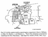
[Maybe some SAE members here can chase down the reference for us?]
NOTE: The diagram does raise the importance of sealing the radiator to keep flow moving along and not "circling back" or becoming cross flow.
And here is another look at the flow in a wheel well:
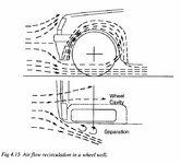
The diagram does lend credence to using the gills or fender louvers to evacuate the wheel well.
Cheers - Jim
These are from Thomas D. Gillespe's Fundamentals of Vehicle Dynamics.
He uses a transverse mounted engine for the bay drag discussion - I'll see if I can find some streamlines from the B-B and C-C cutaway planes:
[Maybe some SAE members here can chase down the reference for us?]
NOTE: The diagram does raise the importance of sealing the radiator to keep flow moving along and not "circling back" or becoming cross flow.
And here is another look at the flow in a wheel well:
The diagram does lend credence to using the gills or fender louvers to evacuate the wheel well.
Cheers - Jim
69427
The Artist formerly known as Turbo84
- Joined
- Mar 30, 2008
- Messages
- 3,080
- Reaction score
- 42
- City & State/Province
- Clinging to my guns and religion in KCMO.
There are metal plates that bolt to the bottom of the fenders and tie them to the bottom of the wheel well... mine (stock?) were steel. Easily replicated in aluminum :amused:
I pulled out the 14 oz steel units and replaced them with 6 oz aluminum pieces. I mounted the sheets at the bottom edge of the frame to help reduce some of the turbulence behind the lower wheel wells.
phantomjock
Well-known member
Good weight savings there.
Project for "just weight" or planning some under hood aero?
Is it open to the wheel well or closed as original?
Are you planning a duct to the gills too?
Cheers - Jim
Project for "just weight" or planning some under hood aero?
Is it open to the wheel well or closed as original?
Are you planning a duct to the gills too?
Cheers - Jim
69427
The Artist formerly known as Turbo84
- Joined
- Mar 30, 2008
- Messages
- 3,080
- Reaction score
- 42
- City & State/Province
- Clinging to my guns and religion in KCMO.
Good weight savings there.
Project for "just weight" or planning some under hood aero? Both. I also moved the location of that lightened panel.
Is it open to the wheel well or closed as original? Closed
Are you planning a duct to the gills too? No. I'm trying not to cut up any of the bodywork anywhere.
Cheers - Jim
I don't know if my experience with the front wheel well air is similar or different than diagram 4.15. My pace car front air dam seems to divert a decent amount of air sideways, and the brake pad dust is definitely making its way outward, so some wheel well air is obviously moving laterally outward, but given how dirty the wheels become from this dust I could be convinced that there is some air separation going on, causing the dust to cloud up near the wheel outer surface. Just speculation on my part, I don't know right off on a good way to measure or confirm it.

mfain
Well-known member
Good weight savings there.
Project for "just weight" or planning some under hood aero? Both. I also moved the location of that lightened panel.
Is it open to the wheel well or closed as original? Closed
Are you planning a duct to the gills too? No. I'm trying not to cut up any of the bodywork anywhere.
Cheers - Jim
I don't know if my experience with the front wheel well air is similar or different than diagram 4.15. My pace car front air dam seems to divert a decent amount of air sideways, and the brake pad dust is definitely making its way outward, so some wheel well air is obviously moving laterally outward, but given how dirty the wheels become from this dust I could be convinced that there is some air separation going on, causing the dust to cloud up near the wheel outer surface. Just speculation on my part, I don't know right off on a good way to measure or confirm it.
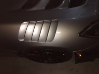
Here is something you can take as tested gospel. The vents above the wheel on the Viper ACR WILL NOT extract air from the wheel well when the louvers are installed. The air is wrapping around the wheel in the direction of rotation and it cannot make the 135 degree turn to exit the louvers. I have tested it with yarn tufts to 150 mph. The same is true of the backwards facing scoops on a 69 Dodge Daytona Charger (when they are opened to the wheelwell). We tested that with ink drops on a Bonneville Salt Flat car. BUT, when you take the louvers out of the hole in the ACR fender, air, pieces of rubber, birds, and small children are expelled straight up out the hole and you can feel the increase in downforce. Also note the two canards in front of the wheel well - they have lips on their outer edge that act as vortex generators and create a low pressure area just outside of the tire. This pulls some air out of the wheelwell and through the wheels past the brakes (good for cooling). The spats on a late Corvette do a little of the same as they create a little bit of low pressure outside of the wheel.
Pappy

phantomjock
Well-known member
Pappy -
It's great to have "real-life" info like you've passed along. I can say from my experience (on the sports racer) there was a noted difference pre and post louvers.
This season, I'll be capturing "real" data to verify. Plan includes A-B testing with louvers, open - and filled. Video and data if I'm really prepared. Tuft testing looks best on video, and less messy than ink/oil-dye streak testing, even if it perturbs the near-field flow.
I note the LMP cars have all migrated to the open fender in lieu of louvers. I had understood it was in an effort to keep them from going airborne when traveling backwards following a spin.
End plates are - and have - undergone a huge amount of engineering for that last 1/10 percent. All seems to have been in the direction which you mentioned, and 69427 has noted, generate a pressure differential. This is most noted in open wheel (F1) as they try and create an Air Fender to reduce wheel/tire drag. Vortex generation efforts can be effective this way and in creating a curtain as we saw in some of the earlier posts.
Back to rebuilding carbs.
Cheers - Jim
It's great to have "real-life" info like you've passed along. I can say from my experience (on the sports racer) there was a noted difference pre and post louvers.
This season, I'll be capturing "real" data to verify. Plan includes A-B testing with louvers, open - and filled. Video and data if I'm really prepared. Tuft testing looks best on video, and less messy than ink/oil-dye streak testing, even if it perturbs the near-field flow.
I note the LMP cars have all migrated to the open fender in lieu of louvers. I had understood it was in an effort to keep them from going airborne when traveling backwards following a spin.
End plates are - and have - undergone a huge amount of engineering for that last 1/10 percent. All seems to have been in the direction which you mentioned, and 69427 has noted, generate a pressure differential. This is most noted in open wheel (F1) as they try and create an Air Fender to reduce wheel/tire drag. Vortex generation efforts can be effective this way and in creating a curtain as we saw in some of the earlier posts.
Back to rebuilding carbs.
Cheers - Jim
Last edited:
rtj
Well-known member
- Joined
- Nov 5, 2011
- Messages
- 3,598
- Reaction score
- 211
“BUT, when you take the louvers out of the hole in the ACR fender, air, pieces of rubber, birds, and small children are expelled straight up out the hole and you can feel the increase in downforce. “
Very graphic description, ACR’s are bad ass cars. Always wanted one.
Duntov sells Corvette louvres with the gills going up above the fender. They each create a low pressure zone.
“The louvers mount up and into the wind stream, and are open at the back. This aids evacuation of hot air from the engine compartment. ”
http://www.duntovmotors.com/vintage-racing-parts-body.php
A backward facing step has been well studied and is sort of analogous to these louvers. It has a low pressure region. Google has lots of plots of the pres distribution if anyone is interested.
Very graphic description, ACR’s are bad ass cars. Always wanted one.
Duntov sells Corvette louvres with the gills going up above the fender. They each create a low pressure zone.
“The louvers mount up and into the wind stream, and are open at the back. This aids evacuation of hot air from the engine compartment. ”
http://www.duntovmotors.com/vintage-racing-parts-body.php
A backward facing step has been well studied and is sort of analogous to these louvers. It has a low pressure region. Google has lots of plots of the pres distribution if anyone is interested.
Last edited:

Kacyc3
Active member
- Joined
- Dec 15, 2015
- Messages
- 28
- Reaction score
- 0
Has anyone done pressure testing on the raised L88 hoods? I am wanting to reduce lift and help vent under hood temp and pressure with this hood. I read the thread and saw the holes cut in hoods before the buldge here

it vents his pressure. With a hood like this
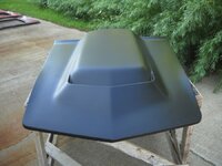
wouldnt this casue a high pressure area and push more air back in the vents?
it vents his pressure. With a hood like this
wouldnt this casue a high pressure area and push more air back in the vents?
Similar threads


- Replies
- 3
- Views
- 1K

- Replies
- 93
- Views
- 22K
- Replies
- 31
- Views
- 10K

