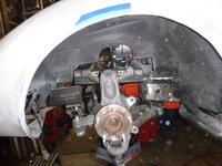
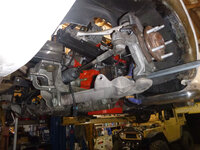
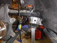
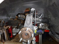
Plastic Fantastic 2

VetteMod - Corvette Restoration, Modding & Performance Forum

Help Support VetteMod Forum:

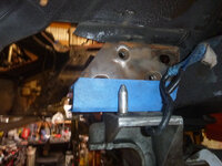
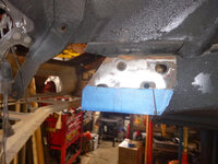
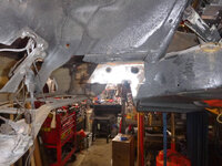
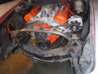
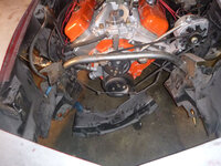
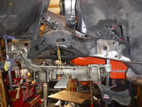
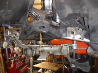
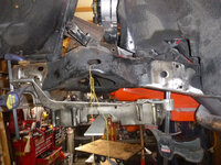
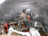
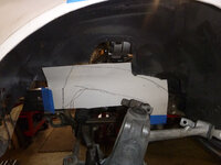
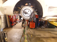
time to clear the space
NObOrOf.jpg

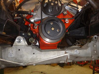
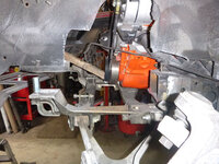
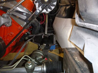
I'll need to build new structure to support the fiberglass... but there is space
xgmWPBB.jpg

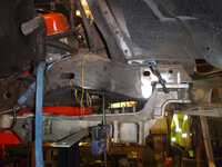
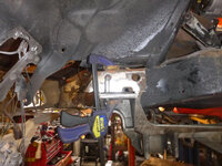
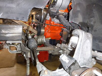
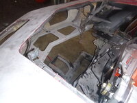
roughly in place.... it needs to move up 2 1/2"
QyZcM1d.jpg
4ylAnoQ.jpg

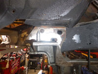
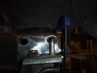
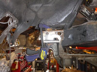
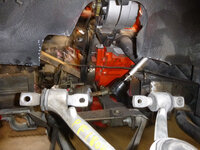
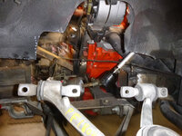
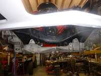
of course, that means removing the cross member
jmIcDtb.jpg

tomorrow I'll build support structure for the frame - most likely that means building some kind of front roll cage then attaching the body to it...edited
 
So more workedited
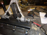
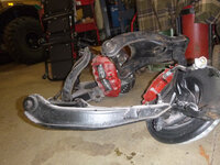
notice how the pivot and the ball joint are on different planes?edited
FrMRxGs.jpg

though the Russian judge will never give more score for it, the C5 has a different spindle height and different pivot plane
cJAGGFU.jpg

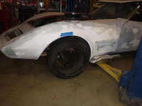
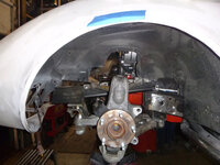
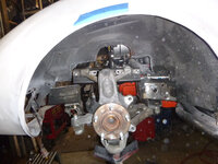
so let's eyeball the problem.edited the ball joint is about in the same place as the C3 pivot would be..... only difference is the center of the hub is 20" away from the fender vs. the 16 or so that's stockedited
vfHl9eZ.jpg

so time to move the frame into the frame
lv6Hz3B.jpg

first cuts
SLCA5AC.jpg

chopped
zb83C8J.jpg

time to weld a brace in place
vcOOYL0.jpg

chopped again
6kUVTRd.jpg
​​​​​​​
now things can move up
SWSCqwO.jpg
r5e41Ko.jpg
and it needs to move back a bit
GBrL6Wo.jpg
 
I'm really enjoying living vicariously through your experience here. Keep the updates coming! :-)
 
so to more detail.
last night I got it more centered - look at the front, bumper bolt hole
iOvedb7.jpg
RwGubN2.jpg

warning if anyone is copying this - those holes are not, exactly in the same spot on either side
2PqsDWh.jpg

another tip - the front control arm hole is 3/4" lower then the rear hole.... this picture is close to where it needs to live
Use the hole where the lines are drawn (rear) - those holes are supposed to be in the same spot on either side.edited That said, trust but verify.
iOvedb7.jpg
 
so more fitting.... I think (hope) it'll be okay to move it up 1 1/2"edited .... I still need to get a legible copy of the suspension points on a C5;
iQ5YzhW.jpg

originally, my calculations showed it here
mlRBgJh.jpg

but I talked myself out of it.... we will see, I'll mock it together before I do any more cutting to doubly verify where the wheel will end (vertically) in the wheel well.edited Even if this is a bit further from the ground the 1/2" at the ball joint won't make much, if any, handling difference.
The other thing... I'm going to eventually cut the stubs off in front of the motor mount and use new metal...edited
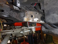
 
I guess you could completely clean up that area, you won't be needing the spring pockets anymore. Good to have for now as you are still trying to verify the right position in relation to what was there before, but is is an unnecessary chunk of weight and complexity once you have it figured out. Are you planning on fishplating in some rectangular tube stubs for the subframe pickup points?
 
As an Amazon Associate we earn from qualifying purchases. Product prices and availability are accurate as of the date/time indicated and are subject to change.
I guess you could completely clean up that area, you won't be needing the spring pockets anymore. Good to have for now as you are still trying to verify the right position in relation to what was there before, but is is an unnecessary chunk of weight and complexity once you have it figured out. Are you planning on fishplating in some rectangular tube stubs for the subframe pickup points?

motor mounts are behind the pockets. I have 4x4 3/16 wall tube, but also I'm close to ready to use my plasma table so if those stars align, we will see.

my current spring plan is use a coil-over-conversion for a C5 so the pockets are not only unnecessary but in the way.... that said, it's a whole lot easier to line things up with the frame in there.

I also plan on removing the frame above the Camaro rear assembly - it's unnecessary too. The body is going to come off enough to clean all of that up, then back together for shakedown, then apart for beautification.... likely this next summer will be the shakedown and the body in black primer.... or red, or grey or whatever is on the shelf...
 
Sounds like a good plan. Without a frame table to work with, I think you probably have gone about this in the best way possible to maintain good dimensional references. It might be more work, but it will be right when it is all said and done. My cousin bought a huge table years ago for frame building. I think it was probably a bed for a large traveling column or gantry style mill. It was roughly 10'X20' and a super heavy casting. It had T-slots in it for work holding, several drilled and tapped holes, etc. He got it for pennies on the dollar as a shop was closing down in Houston and basically paid for the rigging to get it out of the shop it was in. It made full chassis builds much easier, but very few of us have that luxury. He was in the right place at the right time.
 
I have the bits to make a frame table, but after doing one for the Fiat Spider, I just didn't find it was worth the hassle. Granted, if I was doing this for a business, a table would make this happen a lot faster - but my space is limited so it'd probably cost me more time because it's in the way then it would save.

that said, I love those 'must get them out now' deals - it's how I got my lathe.

so a brief note on course a course change

Originally, it was flares and 427. That remains the same, as most who follow know, I love my manual-everything C3s. However, with wide tires, 14" brakes along with a power rack (which I could simply short-circuit), I'm going to add hydraboost to the brakes and plumb the rack and then EFI on the 427. Likely I'll use a throttle-body based system (like FI tech). The reason for EFI is there is a possibility this car is going to get pitted against a C3 with a SBC 427 Corvette and a C3 with a LS 427 - both of which are going to be EFI cars, both of which have updated suspensions.... don't hold your breath for this, though, all of the cars have 2 year min. completion dates....
 
Today, I got a chance to get some good measurements off a C5 Corvette
what surprised me was that the cradle is 5 3/4 inches off the ground.... as of yesterday, it was 8
Bx2xfVs.jpg

255 tire, now 7 1/4 off the ground
Ppz2I3N.jpg

that is about right sitting in the car, yes, it looks low but I could put a 275/20 tire under it ...
eJOWzQS.jpg

time to make it permanent
Rsix8BE.jpg

DEL1Xo0.jpg

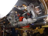
the oil pan is actually above the cradle and the cradle is basically flat to the center cross member (meaning I can do a belly pan pretty easiliy
Oex1AV0.jpg

looking from the back
usvC2FS.jpg

and again the front
DXUwC2s.jpg

next up is the front mount which will include the upper control arm mount.they are 13 inches above the lower control arm in the back 9 1/2 in the front..... basically as the tire goes up the upper arm is moving backward while the lower is going forward- but at different rates.... how the GM engineers figured all this out is pretty fascinating to me, hope it works with the Camaro rear
 
Last edited:
It is fascinating, that's how they work in all the anti-dive, increased Ackermann, etc. When you look at some of the aftermarket front clips that are on the market, you rarely see any of this genius. I would imagine that shows in the handling or lack thereof. Probably not a big deal when you are upgrading a solid axle buggy suspension, but you are upgrading a Corvette here. Taking advantage of the advances in technology over the last 40 years is just good practice. This is going to be a fun ride.
 
It is fascinating, that's how they work in all the anti-dive, increased Ackermann, etc. When you look at some of the aftermarket front clips that are on the market, you rarely see any of this genius. I would imagine that shows in the handling or lack thereof. Probably not a big deal when you are upgrading a solid axle buggy suspension, but you are upgrading a Corvette here. Taking advantage of the advances in technology over the last 40 years is just good practice. This is going to be a fun ride.

My generation went from "never use stock setups" to "use stock setups"... here's my prediction - I blog this, someone out there does a TV show coughcoughaaronkaufmancoughcough then someone else sells a 'new kit' that 'takes advantage of manufacturer engineering' ... again. Thankfully, so far, I haven't had someone who copied come back and try to 'splain' it back to me...

It's fine, though, I think making hotrodding more accessible is always the right answer - and some people don't have the skill or time to piece it together themselves. The whole point of my blogging my builds is a detailed record of what I did and how - whether it's by cash or by knowledge, if someone else gains from it.... that's cool by me. I have a day job that pays far better then what I'd get paid breathing bondo in someone else's shop.
 
Keep up the good work, you are helping to keep this forum alive.

If/When they turn the lights out here, not sure if I would post much at other Corvette sites. Probably just lurk a bit.

Sounds like there is a good story behind some of your comments above. I always gave my ideas at work freely, until one day when someone asked for input, I wrote it up as a patent submission. Ended up getting a few ( company property). You’d be surprised at what people do.
 
Last edited:
Keep up the good work, you are helping to keep this forum alive.

If/When they turn the lights out here, not sure if I would post much at other Corvette sites. Probably just lurk a bit.

Sounds like there is a good story behind some of your comments above. I always gave my ideas at work freely, until one day when someone asked for input, I wrote it up as a patent submission. Ended up getting a few ( company property). You’d be surprised at what people do.

it was a rocky start here, but I like the knowledge base so I keep posting.
 
Keep up the good work, you are helping to keep this forum alive.

If/When they turn the lights out here, not sure if I would post much at other Corvette sites. Probably just lurk a bit.

Sounds like there is a good story behind some of your comments above. I always gave my ideas at work freely, until one day when someone asked for input, I wrote it up as a patent submission. Ended up getting a few ( company property). You’d be surprised at what people do.

The lights won't go out here for the foreseeable future. If VetteMod can serve as an archive for build threads like this, I think it has a valuable purpose. Personally, I use this site as a resource for information, kind of an automotive Wikipedia. Also, I have a ton of pictures hosted here.
 
The lights won't go out here for the foreseeable future. If VetteMod can serve as an archive for build threads like this, I think it has a valuable purpose. Personally, I use this site as a resource for information, kind of an automotive Wikipedia. Also, I have a ton of pictures hosted here.

:thumbs:
 
I mostly lurk on the other sites lest I stir up the wrath of the "experts" there. I like looking at builds for ideas, learning fixes for my own issues, and occasionally if I have something of use I chime in. I chime in here because these kind of builds really get my blood pumping. I don't have much time or $$$ for my project at the moment, so this is all part of the research and motivation phase of my build.

This thread is BIG on the motivation, thank you SBG for that. :1st:
 
critical dimensions

onward
starting to trial fit
A2Dyku9.jpg

good grief there are a lot of layers.... still wonder if it'd been better to just get a front-cut and weld it to the rails... probably would, but since when do I do things the easy way?
ZIQCnBK.jpg

for those doing this - the plane of the edge of the cradle is the inner point of the upper control arms - the actual dimension is (and I may have to correct this) 37 1/4 from bolt face to bolt face... the cradle is 36 1/2 and you need 3/8" per side to clear the inner portion of the upper control arm... the arm itself is 13 1/2 front and 12 3/4 rear above the lower control arm bolts and the rear most arm is 3 3/8 forward of the rear most, lower-control arm edge flange (outside).

that - with 2" flares, is 3 1/4 inedited
VRjzEKU.jpg

note how the center line is in the middle of the hub but the upper and lower control arms aren't...
e15n6rg.jpg

hopefully Sunday I'll get a chance to make all that permanent

I enjoy adding to the knowledge base - and best of all, if I can get someone to say "well hell, if you can do it, so can I" that is winning to me.... I grew up around a lot of people who told me what was impossible :3rd:
​​​​​​​
 
now you see it
4EEnbkO.jpg
now you don't....edited
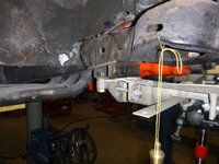
5keVGUV.jpg
might as well keep moving forward front stubs
RQkgTed.jpg
put the rack in place for clearance purposes

6Ap9S6T.jpg

needs to fit somewhere in there
3UOySby.jpg

a bit of CAD work
GX8Kio9.jpg

looks like I need to work on the vertical as well
ajWsuun.jpg
3UOySby.jpg

the interesting bit in all of this is if I decide to LS, it should be pretty much a bolt-in deal
 
So now all I have to find is a power steering pump and brackets.... I'm pretty sure I have hoses left over from the fj40
bbjNlJj.jpg

time to build part of the frame
kb7uKct.jpg
gAc26bq.jpg

I need to find some tube tomorrow and some bolts....edited
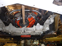
 
more incremental progress
this
kb7uKct.jpg
is now this
H5vXqER.jpg
SrROkcB.jpg

more trimming in the wheel well
1WpbBP3.jpg
mDtBRVT.jpg

and now make it hold itself up
PJG8vBh.jpg

the back bolt lines up with the front edge of the bracket I made
kVFS3s7.jpg

and is 9 9/16 from the bottom of the bolt head holding the cradle in place to the center of the rear-most bolt
front, I can't remember off the top of my head but it's roughly 9 and change above the bolt head of the front bracket.... in real numbers 1 1/2 above the 2x4 I built in the front, 1" below the top of the frame on the rear... (ish).
overall width from flat of the bracket to flat is 39 3/8

front... the upper arm needs to move back about 1" in this picture
mDtBRVT.jpg
​​​​​​​
 
I'm hoping at SEMA I can find a wheel sponsor :)

back to frame mods
aqFHW4T.jpg
P3I0eh9.jpg

eyeballing
wNxcIFU.jpg
faW2Ebm.jpg

WPJoJQM.jpg

kind of sort of where it goes
BMMGCdy.jpg
I know I drive some nuts with how I do this.... here, let me be first to melt your snowflake, I don't care if you like my way or not :)

first is notch the frame - that white line needs to line up with the rear-most bolt on the a-arm
eCwiHr2.jpg

clean
DLcRZyM.jpg
gPRdYw1.jpg

weld nuts inside
yi3BY9e.jpg
weld to piece
mDTCQGI.jpg
3KgCSEW.jpg

I think the front is too low thus the notching you see next
7qpFGXF.jpg

lots of cutting that original notch later
gvAcktd.jpg


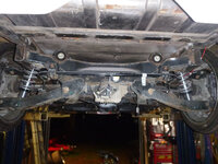
other side - this is pretty close to where it needs to live.... note the angles and diverging bits.edited I think GM thought through all the points of a corner (and I'm going to check this) so that when the car goes right, the tire moves towards the rear tire (basically using the dirt-track method to help the car go left)... thus these aren't parallel with each other, but rather it does several things to help turn
XEATBvW.jpg

​​​​​​​anyway, the answer to that question won't happen until next week....edited
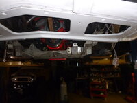
 
back from SEMA, back to work

RguaDhc.jpg

and this is wrong.... this is also why I mock then walk away
9mQjnQu.jpg

still wrong
RHQh1Zu.jpg

this is correct... note how the upper arm moved up about 2"?
JE6MQ1D.jpg

n5hZOla.jpg

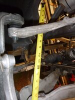
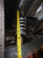
so some dimensions for a coil over manufacturer
ZO9u9LX.jpg

2b28fcj.jpg

U0ZcHd3.jpg

I'm bracing myself for the costs of the coilovers then the wheels then the tires..... cheap or fast....edited
 
I like the “snowflake” comment. If it was an original 63 split window or L88 car, maybe. But that is the beauty of a C3 late model car, prices are low and there are lots for sale in various states of disrepair.

I saw a picture the other day of a c3 race car with a front transverse spring. Probably cheaper than coil overs if you use c5 parts.
 
Last edited:
I like the “snowflake” comment. If it was an original 63 split window or L88 car, maybe. But that is the beauty of a C3 late model car, prices are low and there are lots for sale in various states of disrepair.

I saw a picture the other day of a c3 race car with a front transverse spring. Probably cheaper than coil overs if you use c5 parts.

I like rubber bumper C3s because I rarely get a chalk-sniffer complaining what I did to the car.

I really seriously considered Bob's spring offer - but came to the conclusion that I am not certain enough about ride height to commit to it. There is no adjustment (lowering) for the transverse spring. I met the Senior Product Developer for Aldan Coilovers at SEMA. We talked and now I've ordered a set of coilovers (off the shelf, thankfully) for my car. Since it's Summit where I got it from, expect that picture next Monday....
 
I've been traveling for work, so it's nice to catch up. Looks like you're making some great progress.
 
Looks like c5’s can use lowering bolts, but probably not as easy to change/adjust as coil-overs. Waiting to hear driving impressions.
 
a large part of me (and one that is currently winning) has me driving this in this form this summer then blow it apart next winter for paint, frame welding, and stuff like that

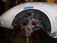
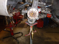
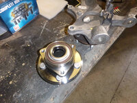
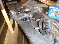
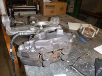
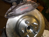
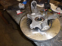
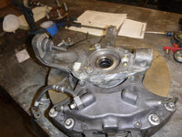
Under the headline, I'll take lucky over good every time.edited Yes, the Camaro unitized bearings bolt directly into the Corvette spindle
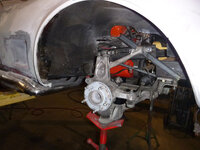
lGftzVN.jpg
dg7SGYo.jpg
601ypYQ.jpg

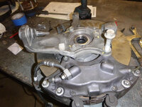
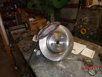
what doesn't bolt is the caliper
Rn27PWw.jpg
only about 1/2" off...
Cxr8d7B.jpg
Uy8QhtO.jpg
trimming is required
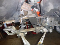
BmtDetw.jpg
a good hack but not enough
VnIgYPj.jpg
that's better
Szae88o.jpg

JsNseVa.jpg
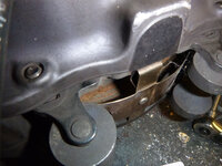
however there's another issue that I don't know if I'm going to (or even can) fix
l2mrJYi.jpg

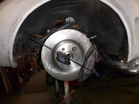
notice the perpendicular to the ground?
not so much up here
S3Tu97K.jpg

before I get too jiggy with the brakes, though, time to finalize the front suspension by yet another round of balls and measures
Xd9KQUk.jpg

A key point here.... at the moment (other then perpendicular upper control arm issue, I'm well within factory tolerance of 1/8".... 1/32 - the key point is this, don't spend your life trying to make this perfect, there are no perfect roads therefore there is no perfect suspension.
 
a large part of me (and one that is currently winning) has me driving this in this form this summer then blow it apart next winter for paint, frame welding, and stuff like that

..........................................
the key point is this, don't spend your life trying to make this perfect, there are no perfect roads therefore there is no perfect suspension.

I agree with your philosophy.

1) I used to paint and polish new stuff when I modified my car. But I quickly found that after some test miles or track days that I was too often just having to grind off the paint to cut and modify/weld the parts to change geometry issues or assembly/serviceability difficulties. Now I just focus on the functionality of the part, and worry about aesthetics later.

2) I also share your thoughts on the lack of perfect roads/tracks.


A question about the Camaro wheel bearing assembly you mentioned earlier. Are there different specifications for those versus the Corvette parts?
 
Back
Top