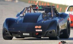
Project Elvira – Intro and Update

VetteMod - Corvette Restoration, Modding & Performance Forum

Help Support VetteMod Forum:

phantomjock

Well-known member
Joined
Sep 2, 2009
Messages
1,925
Reaction score
103
City & State/Province
Retired Again!
Project Elvira – Intro and Update

The following pic is my cartoon work plan. Not so much a spreadsheet or PERT Chart, but a means to capture any method to my madness.
I have had plenty of spare time on my hands while still in physical therapy from my shunt at Sebring last Labor Day. I’ll add a few details on that later.

My 1978 Corvette has followed a number of changes since new. With this major revision, I find it necessary to lay out a plan of sorts and settle on a direction – and help me keep my focus. I can’t guarantee this will keep me from a few, “While-I’m-At-It”, but maybe will keep my ordering of parts organized.

Some of the things I’ve wanted to work include; shifting the engine and transmission aft, raising the differential, lowering the car, dual wishbone IRS, numerous aero-mods, tilt-forward radiator, gull-wing doors, and a few other mad-ideas. As a result, the car will now only compete in SCCA Special Production - Over (engine size)/SPO, NASA Super Unlimited SU. This means Regional-Only Competition. But, I suppose as an A-Mod in Autocross that opens National - hah-Hah! But I have a number of tracks within a 5-8 hour tow/drive to get my fill of track time and empty the bank account.

1269547763128b13a.jpg

For each element of the effort, I’ll start at the nose and work to the tail outlining any progress.
As an outline of my posts – I’ll try and follow this order:
BODY WORK
MECHANICAL/Metal Work
SUSPENSION
INTERIOR
ENGINE
COOLING SYSTEMS
MISCELLANEOUS
SAFETY
PAINT AND FINISH – HAH!
TECH INSPECTION - When finished!!!

I’ll try and follow this maxim:
126954776390c2af4.jpg

Cheers - Jim
 
PJ, why the reverse gills?

Ralphy
Ralphy -
Uhhhh, they look so cool. :D
No, I needed the space behind to mount the oil/transmission radiators. The fit was just too close without reversing.

BTW, I got them from a guy that goes by "Fiberglass Mike." Quality is good and price fair, as I recall. 13Bats has done some work with him - he's here infrequently - a MAKO-guy. Hangs out at the MAKO site.

Good question.


denpo -
Denis - much of the stuff I'll post will be summary, rather than a; "watch while I build it. " Sort of give a fast-forward, to the work already accomplished. I'll try and pace my postings to get some work done at the same time.

MYBAD79 -
Karsten -- Thanks for the encouragement. I hope it turns out half as nice as your work!

Cheers - Jim
 
I just thought since you were reversing/catching air you could duct the air. Say to the brakes, driver, etc...

Edited:
Reading again is that where the coolers are going?

Ralphy
 
Last edited:
As an Amazon Associate we earn from qualifying purchases. Product prices and availability are accurate as of the date/time indicated and are subject to change.
What's the weight target on this project?

Ouch! I'd really like to be at 2800#s. [Wouldn't we all?]

But, I've watched your struggle to get the weight down - while keeping a stock-looking C3. Because this will still be street legal (it is in FL, so a little easier) I'll still do lights etc. Even though the interior is gutted - the cage makes up a lot of the weight. But, the aluminum buckets will shave a pound or two over the stock, or even Sparco seats.
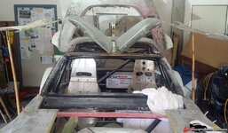
Replacing glass with the lexan is a bennie, and no side windows except for transport - class rules require open.

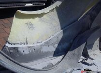
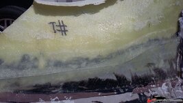
I'm making the flares just now - and keeping their weights down. The first 2 are out of the mold awaiting trim and weigh 3# each -- but still to be glassed to body.

The Gull Wing doors are waiting trim, but they are gutted - no steel bars - NASCAR door bars for that. This next week I'll be tackling that body work - I think.

Aluminum radiator saves some weight. Aluminum heads on the 383 shave pounds off the double humps I had. The Webers and IR intake manifold probably plus up the weight a bit.

Suspension is helping bring some of the weight down - up front anyway. The SPCs are lighter and I believe the LCAs are too. Having the transverse composite spring eliminates the anti-roll bar so a bit of saving there as well.
CV axles weigh in at 20# each vs the half shafts and U-Joints. Got rid of the battering ram, all the pneumatics for the lights etc - so only time will tell what is works out to.

Much longer "skirt" there than I intended. But, the short answer is shooting below 3000# -- lower better.

Cheers - Jim
 
Project Elvira Some Body Work

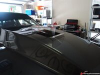
Cowl Induction Scoop:
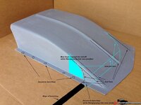
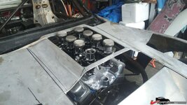
This component is awaiting fairing, sanding, and prep. I got a great deal on a cowl induction scoop but needed to widen it to mate to hood and roll to match radiator exhaust opening.

126954859584ad80f.jpg
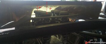
All this to match Weber clearance. I checked with Jim Ingelese (Weber tech-supreme) and he recommended a minimum of 2 inches clearance. Easy for the rear – not so easy for those 4 up front.
12695485958439228.jpg
Drivers eye view:
1269548595853dacd.jpg

This is a BIG cowl:
12695485958472e7b.jpg
I may need to make it out of Clear Lexan in the future. Something like this – but a Cowl Induction.
126954859584f15b9.jpg

But for now, here is how I worked it.

12695485958566711.jpg

Widening was a cut and paste action. Sunny yesterday, so I got working some of the finish. That is just “dry-fitted” and it fits better than in this pic. And the finish is much better now too.

Warmed air from the Radiator may prove to be a problem – so may “turbulate” with a gurney flap – or some “Zs” testing will tell – for now it is, “… sand, fair and sand some more. Press on regardless.”


Jobs current in the garage 7-8 Dec ‘14:
BODYWORK:
Fender Flares 1 complete, second pending
Rear Fascia – the fill in plate for the Kamm-back​

Fender Flares Background/Update
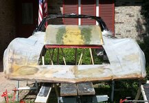
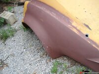
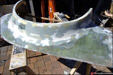
I built the buck in 2012-13. I started with a set of L-88 Mudflap flares from a rear clip (picked up from a buddy in 2009):
126954859298ef3a9.jpg

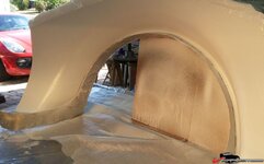
Then cut them and made a dual Mudflap flare. Best seen here.
12695485929949732.jpg
Then I built the mold on the buck:
1269548593a700e3b.jpg

Success! Pulled the new mold from the buck – Now I’ll store the buck in the attic I guess.
1269548593a77b30c.jpg

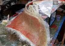
Then, layup a flare in the mold. I added a bit of aluminum flashing to give an inset to the flare [picture follows]. Will look nice, add some strength, but may cut it off after all the effort of working it into the mold, and laying up.
1269548593a7da682.jpg
First flare came out great.

Second had a gel coat fail and I now use it as a reminder of, “PATIENCE GRASSHOPPER…”
1269548593a82c176.jpg
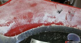
So sand off all the gelcoat from the failed flare, re shoot the mold with tooling gelcoat, wax (7 times), PVA release, then shoot the gelcoat for the new flare.
1269548593a863031.jpg
Today I’ll layup Flare #2.

Other BODYWORK in the Garage:
Rear Fascia Lay-up
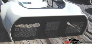
Denis has been wondering about various rear end treatments for his build. I'm partial to eliminating the "parachute:
1269548590de9e6b5.jpg
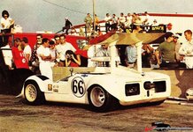
or as seen on the Chaparral:
1269548590deb7132.jpg
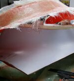
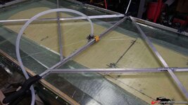
Not much to see here, but the table I used to pull the vacuum on the piece:
1269548590dee66ec.jpg
I built the vacuum a few years back. I was pulling -25psi on the piece nice and flat and smooth as glass. The table is a sliding glass door. I still wax it to aid in release, but no PVA. Any resin run-off is easily cleaned with a razor blade.

That's the update for now. Got my bits for the IRS build back from my machinist - may cover that next.

Cheers - Jim
 
Thanks for the comments and encouragement. Some of what I’m posting has already been completed – or in progress. [The result of me not being focused on posting the efforts until now.] So what is happening now?

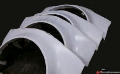
Got four good flares – and a spare to cut up and use for fitting/positioning on the rear and front clips:

12695496f9614af94.jpg

I adjusted my layup schedule, as I made each one so they are slightly different weights. They have been only rough trimmed, and I’ll need to trim the inside lips. The first was just over 5 ½ pounds, and the last right at 4 ¼ pounds. I don’t know how that compares to Eckler’s or ACI, but I am pleased with the output and their rigidity. My work with the buck and mold finished – those are now tucked away in the attic. She Who Must Be Obeyed wouldn’t stand for anymore car parts in the living room. :pprrtt:

A few years back, when I first started asking questions about a dual wishbone build for the C3, Twin Turbo suggested that I just pick a Jaguar rear suspension and be done with it. [ http://vettemod.com/forum/showthread.php?t=7751 ] Well, as you look at these pictures, you’ll see in a bit, there are a few similarities in my execution of my Dual Wishbone C3 IRS.

Here is a Jag IRS:
12695496f7f633009.jpg

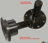
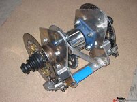
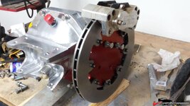
Note the internal brakes. Hmm, that is kinda cool. As I was working out the “how to mate the shaft to the differential” I settled on using flanged output shafts (Tom’s Differentials) and then cut/weld C5/6 output shafts to a companion flange like so:

12695496f7f65cfc7.jpg

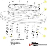
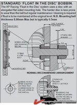
Well a bit of research, and I learned about floating rotor hats, and how expensive they are – but huge advantages. Here is a diagram of one approach:

12695496f7f6e7a23.jpg

And another:

12695496f7f7123fd.jpg

I drew up a quickie sketch and talked with my machinist. He said very do-able.

12695496f7f72c1fb.jpg

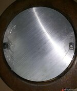
Next day, armed with a couple disks of 6061 T6 Aluminum,

12695496f7f7a1c7e.jpg

my other bits and pieces, C5/6 output shafts, companion flange, and a couple of bobbins, I was off to his shop

12695496f7f76156d.jpg


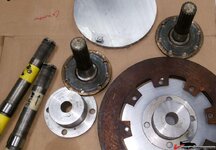
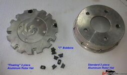
A few days later he had milled the new floating rotor hats, (Comparison of the two shown here)

12695496f7f8165b8.jpg

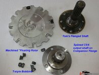
matched the companion flange to the Tom’s Flanged Output Shafts and mated/welded in the C5/6 output shafts in the companion flanges.
Here are the results:

12695496f7f85749c.jpg

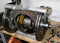
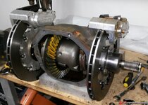
I needed to open the differential to remove and replace the output shafts. Here are the parts pieced together to link the C3 Differential to the C5/6 CV axles. Naturally I couldn't resist mocking the assembly up to see what I'd created:

12695496f7f8a0844.jpg

The brakes will be mounted on a frame and the chassis but well inboard. I’ve calculated (weighed) the resulting difference in un-sprung weight as nearly 16 pounds per side!

12695496fa1ec4061.jpg

Another benefit of inboard brakes, no heating of the wheel bearings from the brakes; when the rotor expands from heat, the floating rotor hat and bobbin assembly allows the rotor to expand. With less stress on the rotor it is less likely to shatter; shorter brake lines are a minor benefit; but, some complain of increased complication to access to change out brake pads – but as the entire rear clip is a flip-up, that should make for better access; and lastly, some complications in getting air ducted to the rotors. The heat will be transmitted to the differential, but I have plumbed and planned a diff-cooler setup and that will help in that regard. Cooling the rotors will get sorted out.

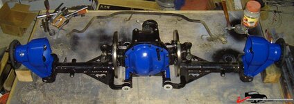
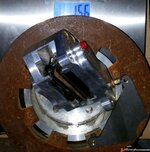
Here I’ve done the fiddling and some detailing of the diff/brake assembly:

12695496f8fc30588.jpg

Now, I need to clean the garage and bring the chassis in in out of the rain and get ready to put the project in suspended animation for 3 months for our trip to South East Asia – I gotta go launch and move the sailboat up to Thailand and get some work done there. I’ll add more of the rest of the IRS build – once I get the chassis in the garage.

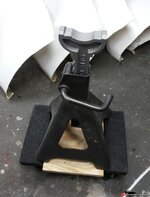
I built some “Rolling Jack Stands” to hold the chassis and let me move it around. [Not seen are the angles I welded inside the 12 Ton Jack Stands, then through bolted the assembly to 1000 pound capacity furniture haulers.]

12695496f8c222f84.jpg

I will weld 4 “receivers" to the chassis to keep the stands secure and be the planned lifting points. Then, I’ll pull and store the wheels and tires, then dry fitting the body for storage.

More pictures and details in next posting. For now, everyone get your Christmas shopping done! :beer:

Cheers - Jim
 
P J what is your addy?? I need do a reverse Santa run out this week and relieve you of your labors there......:shocking:

but seriously, those rotors look to large inboard like that, I ASSume you keeping the same stock upper cross car, not lowering the diffy, much less on the spring mount/bottom end.

:1st::beer:
 
Gene - Better hurry on that Santa Run! I'm west of you - FWB! Those are good questions.

The rear sub-frame is very modified. Tomorrow (or the next day) I should have the garage emptied enough to get the chassis in. Then, I'll mock up the diff, rotors etc., and we'll see where we are. I may have to move the mounting points I was using for the rear toe-control arms, but my tape measure says I have room for the rotors, calipers and mounting bits.

No lower spring - coil-overs on rear now and I raised the diff by 2 inches and removed the cross member and sombrero setup. The diff now is mounted to the aft-most member that is just ahead of the fuel tank, and 2 lower runners of the sub-frame.

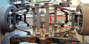
This pic doesn't show well, and those control arms and mounts and uprights have all been changed out now: 1269549736b1afc5d.jpg
I've pointed out where the 2 sub-frame runners are on the bottom, but you can't quite see the mount to the aft cross-member. I'll take new pics in a day or so.

This pic is looking up from the bottom. [Well, really the frame was on its side - but the same view...]

Cheers - Jim
 
We'll go a bit "sideways" now,

Gene (aka mrvette) asked a few good questions about how the inboard brakes, would mount, etc. Ive takes a few pics of the dry-fitting exercise which may help clarify the approach.

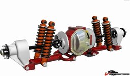
First - a better pic of a Jag IRS:
1269549efd5b81057.jpg
Note - it still uses the half shaft as a key component of the suspension.

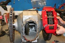
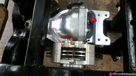
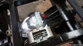
This image sort of zooms-in on the brake and caliper:
1269549efd5bb92bf.jpg
That sort of shows the approach I want to execute and it would require something like the spreader bar seen in this rear end from a Formula 600/1000:
1269549efd5c1da67.jpg
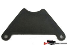
I've got a set of 4 of these to mount to the calipers:
1269549efd5c02cbd.jpg
I'll sandwich a stick of 1/2x1/2 steel tube and that will form the struts to the upper and lower supports seen in the following pics:

1269549efdcef1289.jpg

1269549efd5c758c2.jpg

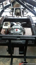
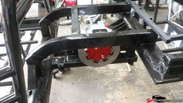
You can see here the brake rotors will be just inside the subframe:
1269549efd5caa477.jpg
(I wish I could say I planned it that way...) :o

In this one you can see the cantilever attachment to the rearmost cross member - in lieu of the typical attachment for the differential:
1269549efdcf20e4c.jpg

Hope those help clarify the differential mounting and integration of the inboard brakes!

Everyone have a Happy New Year! :trumpet::trumpet::trumpet: :beer:

Cheers - Jim
 
Thanks Mate!
I've stuffed it all in the garage for our winter escape for a few months.
But not to worry, I have a few postings to catch up on. I'll drib & drab them to keep you all entertained and engaged!

Meanwhile everyone have a
:trumpet::trumpet: "Happy New Year!" :drink: :drink:
 
Thanks Mate!
I've stuffed it all in the garage for our winter escape for a few months.
But not to worry, I have a few postings to catch up on. I'll drib & drab them to keep you all entertained and engaged!

Meanwhile everyone have a
:trumpet::trumpet: "Happy New Year!" :drink: :drink:

Happy NY to you too, nice work, where did you say you left that??? :1st::beer:
 
wow nice engineering!!!

Damn straight, and $$$ spent too, but I have a question, what is the diameter of the new rotors?? or the old stock rotors for that matter, unless the old stock **** is too large and would hit the spring/cross support, wouldn't getting Toms' to make the new axles with the 5 lug pattern easily facilitate any adapter needed for any 1/2 shaft set up.....and simplify/cheapen up the install?? :beer::p
 
wow nice engineering!!!
AGAIN - Many thanks for those kind comments.
Damn straight, and $$$ spent too, but I have a question, what is the diameter of the new rotors?? or the old stock rotors for that matter, unless the old stock **** is too large and would hit the spring/cross support, wouldn't getting Toms' to make the new axles with the 5 lug pattern easily facilitate any adapter needed for any 1/2 shaft set up.....and simplify/cheapen up the install?? :beer::p

My flight got a weather/equipment delay so I'm still in FL and not just yet enroute to S.E.A. so, I'll work and answer or two.

Gene, the rotors I'm using are are two piece, and are 11.75 inch OD. They match my C5/6 setup, and since I sent the old C3 rotors to scrap - don't have to measure to compare. Also, since I don't have the original differential support member available to compare, I can only guess, but I'd bet the inboard brake option might hit it. [Maybe if I have some time on CAD later, I can draw something out?]
{Small-minor detail: I show the calipers mounted horizontally. My preference is vertical, but couldn't get them to stay still while taking the pictures!}

Yes, a few $$ invested, but I guess that is what I get for trying to engineer this approach - and then revise on-the-fly. Then the inevitable miss-steps on making/placing orders.
EXAMPLE:
The companion flanges - I was able to swap a miss-ordered set with the good folks in Sacramento, but there was the inevitable return postage to pay. Also, my machinist and I have figured a better way of machining the new disks for the floating rotor "hats" and cut the cost in about half. Too late smart...:banghead:​

I checked with Tom's Differentials earlier and he was flat out and not taking on any new projects. I also checked and have had some conversation with Dan at VanSteel - they "might" be interested in a CV axle approach, but were at best on the fence when we spoke. So, I thought I'd sort out the pieces for me and see whats up.

Some of the folks on other forums use Porsche CV axles and Pappy (mfain) mentioned in one the other threads - but I was already well into the C5/6 axles.

As I've sort of experimented with several suspension setups much was on-hand from previous configurations. But the "roll up" looks like this.

So far, this lists the pieces - not the prices:


1 @ C3 4.11 Diff [On-hand, But set up for U-Joints]

Jim's Giovanni Suspension exercise]
http://vettemod.com/forum/showthread.php?t=7705

2 @ Calipers [On-hand, never used] (New Van Steel)
16 @ 3/4" Heims and jam nuts (8 LH + 8 RH)
4 @ 1/2" Heims (2 LH + 2 RH) Toe Control Struts
A BUNCH of Shock Mount Tabs and chassis tabs to mount the Control Arms, and
Way too many hex tube and swedged tube bits and pieces to even count!


First Version IRS - DIY uprights and C3 Wheel Bearings

1 @ Rear Sub Frame [built for DIY Dual Wishbone IRS with U-Joint slip shafts]

Revised IRS with C5/6 Uprights added:
http://vettemod.com/forum/showthread.php?t=7751
2 @ C5 Racing (SKF) Wheel Bearings (New Van Steel)
2@ C5/6 Uprights (Used - eBay)
2 @ QA-1 Dual Adjust Coil Over Shocks
2 @ C5/6 CV Axles (New)
2 complete sets of inserts and machining for each upright
2 sets upper & lower Ball Joints
2 sets Control Arm Mounts to Ball Joints for uprights
2 @Left side (driver's) C5 output shafts cut and welded to the Companion Flanges [This Project]


IRS/Inboard Brake Build
http://vettemod.com/forum/showthread.php?t=10667&page=2
2 @ Wilwood 11.75" OD 8 x 7" 2-piece rotors [Great deal on eBay]
2 @ 8" x 1/2" 6061 T6 Aluminum Discs - machined as floating rotor hats
4 @ Caliper mount brackets (to be fabbed when I return) to mount Calipers
2 @ Companion Flanges
2 @ Tom's Flanged Output Axles/Shafts
16 @T Bobbins for floating rotor
16 @ bushings to mate with Rotor mount holes
16 sets shoulder screws and nuts


So, I can say at this point I've learned a lot, and may have a few approaches I'd change - but will be seeing this to conclusion when I get back. I like the inboard brake concept. I'll be pairing that set up with a brake recirculator system, and blown ducts to work cooling inboard. Those will be fun to work in. I still have brakelines, spot brakes for parking e-Brake and a hydraulic brake (that may/may not work with recirculation), and proportioning valve to install, and the obligatory "roll-control" on the front brakes.

In the next few months, I'll try and post up some of the other work that I've gotten done and some that I will need to finish; Headers and Exhaust, Gullwing Doors (a tease at this point), Chassis and Cage, and some other bits.

Cheers - Jim
 
Just putting into perspective

Gene mentioned $$$.
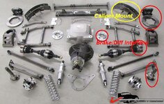
Here is the Heidts IRS - used in mustangs, Tri5s, Camaros, etc.
126954a1d320d0539.jpg

Price, about $9000. PLUS Installation! Whew!


But, it has interesting components and similar approach to what I'm doing:
126954a1d33872968.jpg
I believe what I've labeled as Caliper Mount is just that - maybe not -but very similar approach.

Cheers - Jim
 
I do owe an update. Been Busy – Flew to Southeast Asia in time to miss New Year’s Eve. Then got to work on my other “madness.”
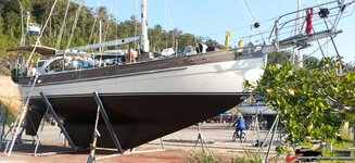
We left the sailboat in Malaysia for the 4 years I was recalled to Active Duty. Last season was a marathon rebuild of the bowsprit, clean diesel fuel tanks (yechhh – 5 years of condensation makes for a lot of slime), new batteries, boxes for them and a bunch of rewiring.
Here is a picture just before we re-launched in mid- January:
126954e2fbcff37d3.jpg

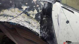
We launched knowing we had engine work to do, so got towed to the slip and got started on working the engine. The diesel cooling system was sludge, slime, and crystalized coolant. There had been some leaks as well in the heat exchanger, so a big effort was started:

126954e2fbd037821.jpg
It would not even start as the starter had suffered from the leaking heat exchanger too:
126954e2fbd072d72.jpg

Turbo, Intercooler, Alternators, and then, the Heat exchanger had to be removed, Naturally , putting it back together was a multi-day effort too. The engine started mid-February, after nearly 5 years of hibernation!

Other chores on the boat sails on, furling gear, anchors, windlass, on it goes. Then a delivery up to Thailand and return to the ‘States early April – and back to Elvira.
I’d post some more, but our wireless on this island is pretty spotty. Once I get to Phuket, it should be better and I’ll add some of the historical details on Elvira, like header design, etc.

Cheers - Jim
 
Enough Farting Around! Time to get back to the Garage!

Ok - I'm back and busy once again on Elvira.
Still working bodywork - trying to get that out of the way and back to mechanicals.
Here's a pictorial update:
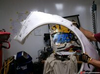
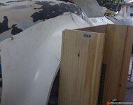
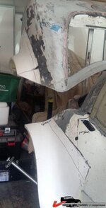
First thing I realized - I'd need to move the split line on the rear clip to ensure the flares would clear the tires when lifting on the hinge:
1269553ab5750df9f.jpg
So that meant glue the rear clip back in position. Also makes it easier to mount the flares:
1269553ab575e3607.jpg But hmm how to make sure they wind up the same on each side? Denis graciously lent me his home made "Tabs" but that wouldn't work for my flares - so I needed to Think Some.
I built a jig!
1269553ab576ad44c.jpg
Heaps of fiddling and looking to be satisfied:
1269553ab6561a94a.jpg
Looks like it might work:
1269553ab6569fb3a.jpg
Well, lets glue them on and get on with it:
1269553ab65902be9.jpg
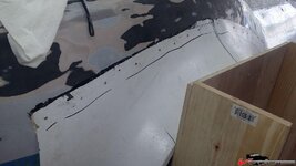
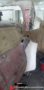
You'll note I needed to re fasten the gull-wing doors too. You'll note the sketch lines for the new cut-lines for the Gull-Wings.
1269553ab659c36aa.jpg
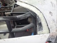
That required some inner "tabs"
1269553ab6579b66f.jpg
With both sides of the rear done - time to re-cut the aft "clip"
1269553ab65ace392.jpg
Yep looks pretty good - on both sides:
1269553ab65b815c8.jpg
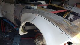
Same technique for the fronts - just a little lower on the body:
1269553ab65c08c9e.jpg
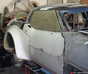
Now cut the Gull-Wings out again - and the windows:
1269553ab65cd421f.jpg
It was a Beach Boys tune that went:"..If she had a set of wings, Man I know she could fly..."
1269553ab69e3d3a7.jpg
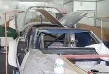
That's been the last couple of days work - time off for a WHO Concert in Jacksonville, and all day today doing clean up and re-enforcements:
1269553ab6d6f412a.jpg
1269553ab6d7ec9b6.jpg

Next its build the front (nose) light boxes - kinda like the Greenwood "shovel nose" on the VetteMod masthead, and tie in the front flares there.

Then, add new split lines to remove the hood. Meanwhile, sort out the hinges for the Gull-Wings, the rear clip mounts and make some "wells" for the over-center latches I picked up to keep the things in place.

Then sand fill, fair, sand fill, prep for paint, remover the body, and FINALLY, get back to some mechanical work.

Cheers -- Jim

Gene If I had time I'd have come over and looked you up too. As it was we spent our spare time "Marina Shopping." Some nice choices on the east side. We may become part-time "neighbors" in a year or two.
 
I do owe an update. Been Busy – Flew to Southeast Asia in time to miss New Year’s Eve. Then got to work on my other “madness.”
We left the sailboat in Malaysia for the 4 years I was recalled to Active Duty. Last season was a marathon rebuild of the bowsprit, clean diesel fuel tanks (yechhh – 5 years of condensation makes for a lot of slime), new batteries, boxes for them and a bunch of rewiring.
Here is a picture just before we re-launched in mid- January:


Cheers - Jim

I used to sail hell outta the Chesapeake Bay outta Annapolis, and points south for years/decades......fishing too off a buddy's power boat....

so much so that I got skin cancer all over me now.....damnit....age 71.....


hit Lonk Ilant south bay too, even the sound, once.....did North Carolina outta the Neuse river too,

and of course a little bit here in Jax Florida.....


gotta love it, GREAT HOBBY!!!!! tons of FUN......nothing like a 36' Catamaran up on one keel and hiking out praying for no flip....

much less getting complimented by a park ranger that he NEVER seen ANY sail as large as ours up in to estuary off a creek where the park was.....we sailing a 20' boat in 2' of water or less....obviously the centerboard was UP....

:nuts:
 
Back
Top