Six Link Rear Suspension

VetteMod - Corvette Restoration, Modding & Performance Forum

Help Support VetteMod Forum:

Stroker427,
I posted the Mustang link mainly for his numbers. I was always asking around. Just how much toe is right? Or close to right for me. In my case I am dealing with a 90" wheelbase, so my guess, I would need a little less. He shows .113 degree or 6.78 minutes @ 1 inch travel and .26 degree or 15.6 minutes @ 2" travel. I averaged left and right. I know you have three inch travel dampers. I have never read anywhere saying you want toe-out under jounce.
 
A couple of thoughts --Toe in roll steer was added to the C-4 Corvette as a safety measure (causes push - understeer) during hard cornering which scuffs off speed and keeps the rear end from coming around. (The C-3 had just the opposite). The Mustang probably got the same "safety" solution from Ford. The Mustang pushes like a dump truck ( I'll probably hear from the Ford guys about that one -- LOL), so I believe that community is adding toe out during roll to "loosen" the car and overcome some of the push. It is simply a crutch, since the real issue is understeer caused by a lot of factors -- too much weight on the nose, too high CG, front suspension geometry, spring rates and roll centers, to suggest a few. If you have enough horsepower, you can always overcome a tight-push condition with lots of throttle, but once you induce wheel spin you kill forward bite -- not the fastest way around a track. As a side note, some circle track guys add a little toe out roll steer to keep the car from starting a push mid-corner, which allows them to pick up the throttle earlier on corner exit.
 
mfain,

KB's site states these rods are for lowering or racing. Guys are lowering the chassis with an IRS? Imagine what that does to the geometry? They're not moving the housing at all I'm sure. They increased geometry change by about the power of 1.5 per inch of travel. Gee then some are running factory springs and dampers? Body roll! Duh! Take your C4 IRS and lower your diff below your hub center-line and see what happens.

How oval track racers toe and camber a solid axle housing.

http://books.google.com/books?id=rY...&q=heating and bending a rear housing&f=false
 
Last edited:
May they have a severe understeer by design...... but I will never like roll toe out in my car!
The risk is when you are late on the apex...... touch the brakes and you will never be able to close the corner!
It looks to me the very wrong way to correct understeer.... and even dangerous!

My opinion, of course!
 
ear plate drawings needed

YES....I need to fab the ear plates and spacers to finish my rear suspension. Thanks....Ken

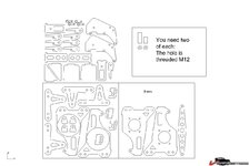
Are you asking about the plates and spacers in this drawing?


That's different, I thought you couldn't download the drawing (but it appears to not exist). The plates and spacers in this drawing?

249b8443428361.jpg
 
As an Amazon Associate we earn from qualifying purchases. Product prices and availability are accurate as of the date/time indicated and are subject to change.
Why can anyone tell me that Strokers bearing carrier is so stout, but that Guldstrand setup is aluminum? Are there any mods to be done in regard with the Guldstrand? Is the Guldstrand flimsy?
 
Why can anyone tell me that Strokers bearing carrier is so stout, but that Guldstrand setup is aluminum? Are there any mods to be done in regard with the Guldstrand? Is the Guldstrand flimsy?

Ralphy:

Guldstrand's set up still uses the half shaft's as a supporting link member. The lateral (Extension and compression) loads are on the stub axles and c clips holding it as a base. Not allot of stress in bearing carrier. Larconi and Riley design utilizes 2 upper link and 2 rear toe link's to hold camber and toe. Much more stress on the bearing carrier's, better design but allot more unsprung weight . GRA3 :cool:
 
Stingxray, I follow you but then again I don't. How does the Guldstrand reduce load under power? Those two lower links add very little strength in this regard. And actually having the rear toe link is a more favorable position in this regard. As I have seen before written, a toe link behind the halfshaft is the best place to control toe and I agree. Only the upper link takes the load the halfshaft once had to support?
 
Which hole to mount to.....?

Which TOP hole on the ear plates do the upper links mount to. Is the 2nd hole needed? I will eliminate them from the plates if they are not. I have the plates drawn up such that a 80-82 design batwing can be used with this system. I will post pics and drawings later after they are fabbed up and mounted to the differential. I will have a 2nd set made (keeps cost down) in case someone wants a set. They will be made out of stainless steel.
 
Last edited:
Anybody had a quote on lazer cutting those parts?

How much would it cost?
Don't forget it will be for two set :smash:

Yeah I know my friend... LOL

BUT right now, I think I'll wait a bit.
675 bucks material included.
Wasnt sure about the thickness soooo it might be cheaper but still.

I havnt shopped anywhere else so well see later.
 
Yeah I know my friend... LOL

BUT right now, I think I'll wait a bit.
675 bucks material included.
Wasnt sure about the thickness soooo it might be cheaper but still.

I havnt shopped anywhere else so well see later.

Is that 675 for two sets? Is that 6mm steel or stainless?
 
Yeah I know my friend... LOL

BUT right now, I think I'll wait a bit.
675 bucks material included.
Wasnt sure about the thickness soooo it might be cheaper but still.

I havnt shopped anywhere else so well see later.

Is that 675 for two sets? Is that 6mm steel or stainless?

That was for one set, SST 304 2B and theres a bit of confusion about the thickness, ¼’’ et 5/16
I just sent him the download and he quoted.

Maybe if I get the SS and use 3 mm like Stroker did I might get away with it fer less,

I'll check later this week
 
Last edited:
That was for one set, SST 304 2B and theres a bit of confusion about the thickness, ¼’’ et 5/16
I just sent him the download and he quoted.

Maybe if I get the SS and use 3 mm like Stroker did I might get away with it fer less,

I'll check later this week

I think the drawing is set up for 6mm and 8mm. Below is the file I got from Yves that (I think) has all the parts in one file. The two boxes on the bottom are 8mm and the upper left parts are 6mm (guessing again). I don't know if there are any 3mm parts. Maybe Stroker will see this and clear up these issues.

The waterjet/laser cutters usually put a setup fee in the job so the second set of parts are usually cheaper. Also the plates are stacked so you might be able to get the second set for material cost plus a litle extra for the slower cut. Stainless is probably 30-40% higher than steel plate also

44f6df5f5e2181.jpg
 
Late reply

Anybody had a quote on lazer cutting those parts?

How much would it cost?

Good-day Michel and All : (got your PM Michel)

Where does the time go ?
I had the Stainless cut by my cousin in 2009. He had a water jet business at the time, charged me $275 for 2 sets. He cut it in one pass with the material stacked and a technique called "Nesting" which reduces waste material. Sorry to say he sold the business due to lack of business.

I'm knee deep on projects right now and the reason I haven't been on the forum for a while. As for the Pier Paolo build ...I Finally got the Urethane bushings machined for the cross member. I have to weld in the sombrero supports brackets ...then things will start moving again . GRA3
P1000573.jpg
P1000574.jpg
P1000575.jpg
P1000576.jpg
 
Last edited:
I Finally got the Urethane bushings machined for the cross member. I have to weld in the sombrero supports brackets ...then things will start moving again .
P1000576.jpg

Interesting, are these available for sale? I have a wheel hop issue that I would like to solve, maybe something like those bushings instead of the stock rubber could help.
 
Interesting, are these available for sale? I have a wheel hop issue that I would like to solve, maybe something like those bushings instead of the stock rubber could help.[/QUOTE]

Sorry .....No one makes these.:confused2::twitch:
I had to do all the work Ie: take measurements , buying the materiel $ 85
(http://stores.ebay.com/Best-Source-For-Urethane-Products) Bribe the machinist to do the lathe work ( ie : Donuts ). That's why this car is now on the 15 year plan. :huh::cussing:
 
Last edited:
I'm interested to know how many of you guys finished this conversion and what you think of the outcome. Looking to do something to my rear suspension, just not sure how far I want to go.

Also, does this setup use standard rear leaf spring and sway bar, and does it give any additional clearance for wider rims?

PS. excellent thread.

Thanks,Doug
 
Last edited:
In my car I have coilovers, but the system was designed to work even with leaf spring.

Yes, the system allows wider rims..... now I have 10.5" wide rims (from a C6) at the rear..... everithing is very close, but it works!
By the way the wheel is exactely flush with the rear stock fender of my 79.....
 
Yes, the drawings in the previous page is the 6/8mm release.

Now I have in my car the second release which is done all in 3mm Stainless with multi layers in the more stressed areas.

After several track days, several drifting sessions, several xcross..... and after zillions of holes and bumps in the road, nothing is broken! :yahoo:
 
Thanks guys. This is certainly a great looking setup, may be a bit of overkill for the street. Will have to give it some thought.

Doug
 
Anyone think about doing the bearing carrier portion in aluminum? Im going to assume the diff bracket has to be steel since the control rods are mounted in single shear unless someone has any ideas to make an aluminum diff bracket work
 
I had two sets cut out when I got mine. I'm still waiting for the bearing holder, but I'll have one extra when they're done. If anyone wants to buy, I think the cost was about $300 each. I had them cut out of 3/8" steel - which means it's thicker than 8 mm so the notches need to be opened just a bit where they join.

oh, and if there's enough interest, I can get more cut out by just placing a phone call. They do not have the capability to do thick enough stainless (think their limit was 1/4")

PM me if interested.
 
Sting,
I'm very very happy to see the progress in the job!

A small suggestion coming from my experience.... make an other hole above the original one in the lower portion of the brackets which is going in the frame pocket.
Then use to higher one of the two in the upper area of the same bracket for the other link.

The front pivot point of the lower longitudinal link will rise, rising the end of the swing arm.

After you istalled the system, try to play a bit with the longitudinal links lenght.... this can help changing the reaction force when braking.

I did it and now I have less squat and zero wheel hop when braking!

Hope to see your car sitting in the wheels very soon.....
 
Back
Top