Six Link Rear Suspension

VetteMod - Corvette Restoration, Modding & Performance Forum

Help Support VetteMod Forum:

Yes........ MYBAD79 those are the ones that Tatton's made for me.
If you interested.......... Ill look for my invoice number, so they can look it up and match . :thumbs:

oh well.... here I am going to spend another $425 on this car...... :smash:

thatnks for looking up the number... the 1350 joints fit the stock yokes, correct ???
 
the second is that i failed to improve the front suspension bushing setup so that they match the rear which is almost completly solid with this setup.


I was wondering about this, how about installing these instead of solid rod ends

http://www.speedwaymotors.com/Mr-Roadster-4-Bar-Rod-Ends,25122.html?parentDisplayId=1583

Still make the bars adjustable ..

Would this make it a bit less racey and a bit more street?

Don't know, but I have either the stock arms or the VBP offset arms to convert, so these are not an option, unless, i completly make a new arm.
 
I know it has been posted here. But can someone give me a name as to who can manufacture the splined two piece half shafts in the states?

Thanks,
Ralphy

Had mine done by
TATTON'S DRIVESHAFT'S
curtis. 1-801-685-0056

425.00 for 2 driveshafts. both with the 1350 slip and spline
and a 1350 weld yoke on the other end ,with the 2 1/4" 250
wall tubing and the solid spicer ujoints. shipped to you.

http://stores.ebay.com/TATTONS-DRIVESHAFTS?_trksid=p4340.l2563

I used 2nd gen Viper shafts and had them shortened and balanced for $100. I have an extra set (unmodified) if anyone is interested. All Spicer components, good stuff.
 
Piere,
The rear toe rod, is it equal length to the half shaft or is it longer?
I have recently noticed the C4 design is longer. I'm guessing to add toe in with travel to reduce over steer?

Ralphy

Thanks BB! 4-10-11
 
Last edited:
The solution is not how long is the arm itself, but how it works with the other rods during the wheel travel.

Anyway the toe rod is equal to the lower rod..... the upper is shorter in order to have a small camber gain.

As you can see in the hub there is 3 holes, changing the outer pivot point will change the roll/bump steer/toe.
The higher hole will give you less roll steer..... the lower will give you more.
In my test I have seen that the lower hole will make the car very roll sensitive.... so I suggest to use the mid one or the upper one.

Keep in mind that the whole system is designed with very short wheel travel in mind !
 
I guess the term I should have used is bump steer. Looking at the pics it appears the top hole would be about parallel to the halfshaft and give the least bump steer/roll steer/ toe? I'm with a 90" wheel base so I'm sure I would be more twitchy! This design in regard to roll steer, toes the loaded side in and the unloaded positive?
 
Last edited:
The halfshat is not involved in the wheel control, so it's position don't matter.
The position of the toe rod is higher that the lower rod.... so it will works in relation of both uper and lower rods.

Yes, the design toes a bit the outer wheel (roll, for the outer wheel, works like bump).

Sorry if I keep saying that the system is designed for a quite short stroke suspension.
My coilovers have a stroke of some 3 inches..... and they are mounted with a ratio close to 100%.
 
Yes I did forget in my mind the halfshaft is no longer a member. As far as your 3" travel damper at 100%. I am looking at Pro Shock, they have a 4" travel 9X13 narrow body coil over. That is three position adjustable. I think they said it uses a 1 7/8" ID spring. If I see no advantage I will use a standard diameter coilover. I am really fighting for space in my kit car! I haven't seen to many setups that get nearly 100% travel from coil and shock as Corvette does.
 
In my setup I use Penske 8300 series Coilovers with 3" stroke and 2.5" springs.

A bit pricey..... but they work very well!!!!!! ;-)
 
Question ?...............

Congrats......! Pier on the Magazine article . It's a nice write up . I have a quick question for you. Do you remember the approx. length of your stand- off tubes on the differential bracket's? The tube length looks to be 2" forward tubes and 4 inches to the rear. Judging by your photos. Thanks ;)

suspension1.jpg
 
The shorter one is 40mm and the longer is 70mm..... sorry, we use metric units! ;-)

That's OK, the cognescenti can use both units interchangebly and to advantage....:clap:

Yes we do ........70 millimeters = 2.75590551 inches and 40 millimeters = 1.57480315 inches.... I was pretty close :flash::bump::thankyou::sos::stirpot::zzz:
 
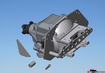
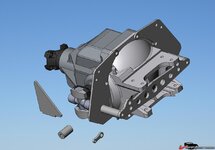
Problem with the differential plate drawings

I have all of the parts for the six link housings made. I cannot download the drawing page for the differential plates and standoffs. I am using Autocad 2000. Could someone please either update the drawing set or at least post the drawings such that I can make the plates and standoffs. Thanks.....Ken
 
The drawings all open for me in Autocad 2000 and R12. These are the oldest versions of Autocad I have, I don't think the files need to be updated, that will only make things worse for people using older Autocad. Let me know which file you are having trouble with.
 

Attachments

Files needed

The drawing files that I need are those of the differential mounting plates with the standoffs that mount to the bolt pattern of the differential houding. I do not see them in the 3 drawings listed above. I have those 3 drawings and they open up fine. Ken

The parts that I need the prints for are in the picture in Post #49......
 
Last edited:
That's different, I thought you couldn't download the drawing (but it appears to not exist). The plates and spacers in this drawing?
249b8443428361.jpg
 
Hi guys, this may sound a bit dumb but how does the adapter to convert the trailing arm to twin links bolt or weld to the TA pocket area?

Cheers,
Matt.
 
Welcome Bad Bird, that's a very good question. I believe it's bolted and welded in. TT can probably offer some help. You probably use the original mounting hole to locate the bracket and then position and weld.
 
Bad Bird -
If I get your question right - it sounds like you're asking about a 4 link to replace the trailing arms...
Here is a link to a setup that autofab has for that:
http://www.racingjunk.com/Suspensio...version-.html?imageIndex=1&showSuperSize=true

You'll note the curved section - that would be welded to the chassis. Most of the DIY 6 links keep the trailing arm as is, and build brackets to control camber/toe.

Also, it seems like most 4 links are used with a live axle and not an IRS - and for Drag - not track/autocross.

Hope that helps.
Cheers - Jim
 
Differential ear plate drawings

Did anyone find the two ear plate drawings for the six link along with the spacers. I inquired a while back and they are not in the drawing section. I have all of the parts fabbed up but these. Thanks.....Ken
 
I'm not sure with this guys idea, he wants to toe out his IRS in regard to roll steer. However he measure his roll steer, .050 according to him equals .180 degree of steer. This kit he shows from what I gather is actually for guys who lower their rides and it corrects the geometry.

http://mdmustangs.com/David_Simmons_Cobra/irsbump.html

I now understand rear steer is referred to as roll steer. Searching this term I have found conflicting info. In a book titled, How To Make Your Car Handle. It suggests racers not use roll steer.

http://books.google.com/books?id=cr...ndependent rear suspension roll steer&f=false
 
For my opinion is a very bad idea to look for bump-oversteer in the rearend!!!!

You will never be able to apply some throttle coming out from a corner...... roll-steer is the same thing than bump-steer.

Applying throttle will cause some squat (unlees you are driving a dragster...... but n this case why to talk about corners???) at the rear, causing toe-out....... no way to drive fast!

You may need the opposite...... for my experience.

In some autocross I setup my rearend with a lot of toe-out but in rebound (braking..), in order to be very quick at the beginning of the corner...... and then a good quantity of toe-in in bump (accelerating..) to avoid power oversteer.

It looks to me that he is doing the opposite..... mha!

IMHO......... of course!
 
Back
Top