Rack and pinion - homemade Steeroids with GrandAm rack

VetteMod - Corvette Restoration, Modding & Performance Forum

Help Support VetteMod Forum:

Gene, no rush !! Thanks for getting the measurements but it does not have to be tomorrow AM :)

I know it is possible to position the rack and use only two joints, just have to find that position ...LOL
 
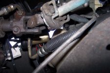
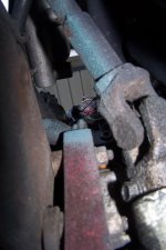
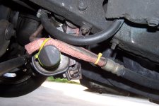
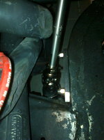
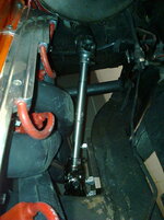
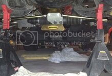
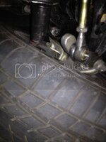
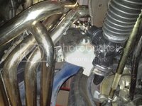
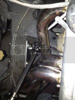
From top of steering tube to bottom of frame is 3" from steering tube forward to the A arm FACE in rear, not the lower lip, is 6" , I can't clearly show that the lower engine arm was cut next to the frame to get the rack input up in the air, and relax the angle on the joint at the column end, still a stiff angle, but it's been that way for years now....Excuse the fugly red hose, but it's just to keep metal off metal, that's all....

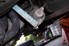
you can see the spacers off the frame that are almost 1/2 inch that helped locate the rack and made mounting the bracket easier....you can see on the first pix just above the lower clamp/bolt the hole where that angle brace to the bottom of the frame was made it was bolted there, we thought to weld it later on, more secure, so the bolt was removed....

All I know is that the brackets do not move with tires on the ground and wheel being turned, manually or with engine/steering running, I fail to see why any support is needed between the brackets, as the one on the passenger side is just to hole that end of the rack, in fact the rack can easily slide back and forth on that end.....but there are no rub marks/traces of that happening....the U brackets came off the Grand Am so they are stock as a stove, except where one tab was bent and the bolt in vertically for better ground clearance on the right side.....
 

Attachments

  • steering 004.JPG
    steering 004.JPG
    512.1 KB
  • steering 008.JPG
    steering 008.JPG
    596.7 KB
  • steering 009.JPG
    steering 009.JPG
    435.3 KB
  • steering 011.JPG
    steering 011.JPG
    643.4 KB
  • steering 002.JPG
    steering 002.JPG
    698.1 KB
Check this out, maybe it helps. It´s thight, but it works! You have to shorten your steering shaft as much as you can. You can do this by collapsing it.

16422813el.jpg

16422814hj.jpg

16422815yp.jpg

16422816id.jpg

16422817zz.jpg

Regards, Günther :cool:
 
Awesome, thanks guys !!!! I think I learned two things: Gene's U-joints seem to be able to handle more angle than my FlamingRiver joints .... Gurnther managed to position the rack even further back withthe collapsed steering column ....

At this point it seems that if I collaps the column I get all the clearance and improve the joint angles ....

Gene: 6" from the A-arm to the tube, going to check that tomorrow
:thumbs:
 
Awesome, thanks guys !!!! I think I learned two things: Gene's U-joints seem to be able to handle more angle than my FlamingRiver joints .... Gurnther managed to position the rack even further back withthe collapsed steering column ....

At this point it seems that if I collaps the column I get all the clearance and improve the joint angles ....

Gene: 6" from the A-arm to the tube, going to check that tomorrow
:thumbs:

Just to be clear, that is an even 6" from the back FACE of the LCA, not the bottom flange sticking out flat horizontal on the bottom, but the vertical part....and yes, my column was a later shark column almost from the beginning up north yet....this conversion done down here some 6 years after buying it.....and as such at some point, I moved the column back off the firewall about 3/4 inch or so, sealed it in, to bring the wheel toward me about much as possible, that also has the same affect as collapsing the shaft more.....and relaxing that upper universal...every degree helped....

Don't quote me on this, BUT, I maybe took a grinder to the joint up top to alleviate some hitting, allowing more angle.....but there was SO much cutting/testing/grinding/modifying on this project that went on for well over a month, I just can't remember every damn detail....

I know I have posted the sketches of the brackets here, some time ago....

:trumpet:
 
ok....... ******* me..... I did not collapse the steering column so that explains why my Ujoints are binding.... I think if I move the upper Ujoint 1" back towards the firewall the angles will be perfect....

:tomato:


here's a pic that i found online, looks like there's at least 1-2" difference


215280eb4d5c960.jpg
 
Last edited:
As an Amazon Associate we earn from qualifying purchases. Product prices and availability are accurate as of the date/time indicated and are subject to change.
ok....... ******* me..... I did not collapse the steering column so that explains why my Ujoints are binding.... I think if I move the upper Ujoint 1" back towards the firewall the angles will be perfect....

:tomato:


here's a pic that i found online, looks like there's at least 1-2" difference


215280eb4d5c960.jpg

Waitaminute!
I know this filthy garage ground....:huh:
Guess I'm getting kinda famous, just like when I image search for "'turbine wheel" and pic on my wheel is within 10 first find....

FYI the picture was depicting how collapsed was the white one, check the mounting ears being misaligned. That's why I had to dismantle it, in order to decollapse the tubes (and not the shaft).

EDIT: hurray, I managed to get firefox installed at work, and now I can post again!!!:yahoo:
EDIT2: the shaft on the black column on have been collapsed to accept a Borgeson steering box FYI
 
Last edited:
PROGRESS !!!

I collapsed the column which turned out to be rather simple, a few whacks with a hammer and it's done..... The column moved approximately 2" back towards the firewall, the Ujoint angles are far from binding, looking really goood

I think I'm going to replace the lower steering column bearing, anybody done this? I hope this is simple now that the header and the clutch linkage is out of the way, seems stupid not to do it now .....

The tire might hit the rack on the driver side although my rack is placed 1" further towards the front than Gene's..... We'll see how this goes.....

I have a little more grinding to do on the engine mount and then weld a piece of pipe in there to restore stiffness....
 
I was trying to compare your lateral placement to mine, and due to camera angles, and ****, it's hard to tell from the pix.....my only comment is that the input shaft is about as close to the frame rail as can be, the wheels/tires on my car kept the same wheel centerline as stock....and 255/50/17 up front....they do not rub, because I added about 1/2 inch to the stops on the lower A arm....and still have a shorter/narrower steering radius than my C4.....

:clobbered:
 
Replacing the lower steering column bearing is fairly simple and I highly recommend it to do! That´s also an important part for a thight steering.

Regards, Günther
 
Bearing and plastic retainer are on their way :thumbs:

Those parts will fit any steering column from the GM and 1/2+ of the Chrysler line up for decades.....I"d imagine your local parts house would stock them....

:gurney:
 
Got the bearing and retainer today, pulled the old stuff, installed the new and voila: no more play, no more slop..... Now that the header and clutch linkage was out of the way it was a easy 10 minute job..... Well worth it....

I bought the parts from GMpartsgiant.com, found these guys on Google shopping when I put the part numbers in the Google search.... They were not the cheapest on the parts but shipping was reasonable, they sent it in a flat rate box and I ordered Tuesday, received parts on Thursday, cannot complain....

I tried GMpartsdirect but shipping was inflated to $15... BS !!!!

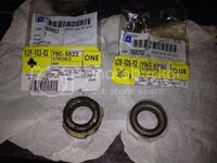
These are good quality GM parts (yeah, I know, doesn't sound right....) and not some cheapo ill fitting pieces from PepBoys.... Like I said, I installed these parts tonight, they fit tight and there's no more slop on that shaft.... The bearing is a very tight fit into the plastic retainer but that's just what it needs to be, there is quiet a bit of feedback on the net that it requires a vice to press the bearing into the retainer: that is not a bad thing.... It fits tight because it fits correctly !!!

Here are the part numbers ... Old bearing and new bearing, old retainer is yellow, new retainer is white:

photo_zps4f19c868.jpg
 
Wow, that's something that never occured to me. Perhaps I should do that 'while I'm at it' doing the box & coupling & PS components. What's involved?
 
Wow, that's something that never occured to me. Perhaps I should do that 'while I'm at it' doing the box & coupling & PS components. What's involved?

Not much.... There's a wire clip and a dust cap, once you pulled these off you simply pull the retainer and the bearing out (leave the bearing in the retainer), clean, grease, pop the new stuff in there, put the dust cap back on and clip the wire back in place....
 
Update:

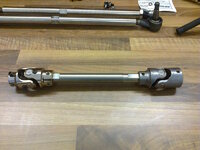
Cut a new doubleD shaft because now with the collapsed column I needed a longer one.... Installed the DD shaft, bolted the rack in place.... Connected the tie rods and voila: turned the steering wheel and no binding at all....

Here's where it's at as of tonight:

photo_zps47ec0531.jpg

.
 
How thick is that adapter bracket the tie rods are tied to??

it looks like it's really thin.....


:chinese:
 
How thick is that adapter bracket the tie rods are tied to??

it looks like it's really thin.....


:chinese:


3/16" with thick washers welded to it on the back side.... Before I welded the washers to it it took a 10lbs mini-sledge to bend it ...
 
just an observation

Karsten,

Judging by your picture and the reports in previously bump steer posts it looks like your tie rods are longer than the ideal length. Maybe we'll get some pivot to pivot dimensions from Gunther bump steer measurements.

Grampy
 
Yes, the tie rods are about as long as they can be. This is a copy of Gene's setup (minus the inner ball joints)... I am using stock style outer ball joint (tie rod ends) at the wheel, rod ends at the inner location....

Guenther uses the adapter bolts to lower the outer rod ends, another interesting different approach....

I also have the square tubing center link for the stock length tie rods, once the car is drivable I'll swap the center links back and forth to see what I like best....
 
Progress .... Slow but somewhat steady ..... Lol

I got the car down on the ground and off the jackstands, steering effort is absolutely acceptable at standstill - I was concerned it might be too hard to turn the steering wheel but so far I have to say, it could not be better : there is no play whatsoever in the steering, effort is hard but not too hard ....

And there's still some clearance to the 275/40 tires :

photo_zps28c531ec.jpg

The brown truck delivered these brand new MOOG tie rod ends today :)

View from under the car:
photo_zps599a1ea4.jpg
.
View from top ....

photo_zpsb6f4e165.jpg

Header clearance is plenty .... Damn, looks like I built something that works :)))
 
Last edited:
Progress .... Slow but somewhat steady ..... Lol

I got the car down on the ground and off the jackstands, steering effort is absolutely acceptable at standstill - I was concerned it might be too hard to turn the steering wheel but so far I have to say, it could not be better : there is no play whatsoever in the steering, effort is hard but not too hard ....

And there's still some clearance to the 275/40 tires :


The brown truck delivered these brand new MOOG tie rod ends today :)

View from under the car:

.
View from top ....


Header clearance is plenty .... Damn, looks like I built something that works :)))

:nuts::bump::nuts: Good show man,
 
Last edited by a moderator:
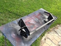
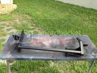
Welded the crossmember in, added gussets, sandblasted and sprayed a good coat epoxy .... Making some progress here ....

photo_zps71151b4a.jpg
.
photo_zps9cee28d5.jpg
.
 
:nuts::bump::nuts: Good show man,

Yup..... Now that I know this stuff works I'm going to make it look good :D

Oh boy, this is a lot of measuring, cutting, fitting, cutting again, **** don't fit, measure again, cut again, **** cut too much, now too short, try again, new piece , cut , weld, cuss.....

You know, that $1299 for the Steeroids kit doesn't sound too bad right now, too bad their crap is so flimsy.....lol
 
The crossmember you welded in looks verry interesting. Can you make a pic of underneath the car how to see the crossmember looks like?

Günther
 
Back
Top