Rack and pinion - homemade Steeroids with GrandAm rack

VetteMod - Corvette Restoration, Modding & Performance Forum

Help Support VetteMod Forum:

outer rod end hiem

The reason for the tapered bolt and use of an outer heim joint is to tune the bumpsteer. Whith a staight thru heim joint one can shim the joint center position higher or lower on the bolt by using cut to length spacers. Part of the classic fix to dial out C2/C3 bumpsteer is to lower the outer tie rod pivot point. You can get dust shields for heim style joints at Summit. If you go with heim style ends use a safety washer.

Grampy
 
The reason for the tapered bolt and use of an outer heim joint is to tune the bumpsteer. Whith a staight thru heim joint one can shim the joint center position higher or lower on the bolt by using cut to length spacers. Part of the classic fix to dial out C2/C3 bumpsteer is to lower the outer tie rod pivot point. You can get dust shields for heim style joints at Summit. If you go with heim style ends use a safety washer.

Grampy

I have YET to spot a factory car with heim joints in the steering/suspension....

I STILL have this nagging thought that the stock style ball/stem/tapered joints are used for decades now for a very solid reason.....and be damned if I going against that....that is a primary wear/weather/water point asking for failure if there EVER was one.....pardon my paranoia.....

:hunter::club:
 
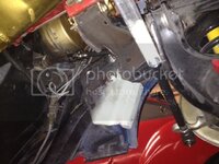
Moved the rack another inch over to the driver side to get rid of the binding in the U-joints. I am beginning to think the three U joints is not all that bad a idea, it is tight with only two U-joints........... Anyway, pretty much got it done, tack welded everything in place, will be installing the header next and then the cross-brace between the driver and passenger side brackets, want to make sure it is not interfering with the exhaust.....
 
Moved the rack another inch over to the driver side to get rid of the binding in the U-joints. I am beginning to think the three U joints is not all that bad a idea, it is tight with only two U-joints........... Anyway, pretty much got it done, tack welded everything in place, will be installing the header next and then the cross-brace between the driver and passenger side brackets, want to make sure it is not interfering with the exhaust.....

Why the cross brace between brackets, it does nothing.....:smash::eek:
 
Why the cross brace between brackets, it does nothing.....:smash::eek:

The two brackets are rocksolid, the cross brace connects the two just like the Flaming river cradle - it ties the front frame together and eliminates most of the flex in this area. Even that tiny spreader bar between the upper A-arm mounts makes a huge difference, I expect this cross brace to help stiffen things up a bit .... it's a 35 year old frame so it's not as solid as it was when new....
In addition: eventually the '79 will get a rollcage. The cage will extend thru the firewall and the location where the front two pipes connect to the frame is about in this area where the rack sits....
 
Why the cross brace between brackets, it does nothing.....:smash::eek:

The two brackets are rocksolid, the cross brace connects the two just like the Flaming river cradle - it ties the front frame together and eliminates most of the flex in this area. Even that tiny spreader bar between the upper A-arm mounts makes a huge difference, I expect this cross brace to help stiffen things up a bit .... it's a 35 year old frame so it's not as solid as it was when new....
In addition: eventually the '79 will get a rollcage. The cage will extend thru the firewall and the location where the front two pipes connect to the frame is about in this area where the rack sits....

You got that huge chunk of frame cross piece in front of the harmonica balancer, where the lower A arms attach, that's going almost nowhere, with the top additional cross support....that front is stiff as my dick used to be....

:rofl::smash::eek: All I did was triangulate off the lower rail on the driver side....
 
Last edited:
As an Amazon Associate we earn from qualifying purchases. Product prices and availability are accurate as of the date/time indicated and are subject to change.
You got that huge chunk of frame cross piece in front of the harmonica balancer, where the lower A arms attach, that's going almost nowhere, with the top additional cross support....that front is stiff as my dick used to be....

:rofl::smash::eek: All I did was triangulate off the lower rail on the driver side....

yet you still say the spreader bar made a huge difference .... That bar sits right in plane with the factory frame crossmember .....
 
You got that huge chunk of frame cross piece in front of the harmonica balancer, where the lower A arms attach, that's going almost nowhere, with the top additional cross support....that front is stiff as my dick used to be....

:rofl::smash::eek: All I did was triangulate off the lower rail on the driver side....

yet you still say the spreader bar made a huge difference .... That bar sits right in plane with the factory frame crossmember .....

Correct, and so any additional support like along the rack, or tying the rack supports together I think is superfluous...department of redundancy department....especially since the support on the pass side is just a round doughnut that can slide on the tube, having no flange to catch like on the driver side....:bounce:
 
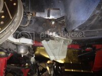
Made a little progress: the driver side is done, drilled the holes in the frame for 7/16"-20 bolts and guess what.... There's already a pipe inside the frame to keep it from collapsing when tightening the bolts.... Great, less work for me, I was going to weld pipes inside the frame.....

Anyways, I moved the driver side mount 1" over to the driver side to get a better angle on thevsteering shaft Ujoints and eliminate binding. I also cut a good size hole in the motor mount to make room for the shaft. A reinforcement plate is currently being "designed" :D

photo_zps9deea011.jpg

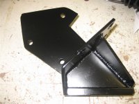
Here's the outside of the bracket with the gussets added.... I am confident it won't flex .....

photo_zps1a797440.jpg


.
 
SWEEET - looking forward to a full set of "revised" templates/plans - (download section?).
Very nice effort Karsten! And. impeccable execution as always.

Cheers - Jim
 
SWEEET - looking forward to a full set of "revised" templates/plans - (download section?).
Very nice effort Karsten! And. impeccable execution as always.

Cheers - Jim

Thanks :)

I am actually realizing that there's no perfect solution for this, just two compromises.....

You can either have the rack centered and use two equal length (20") tie rods .... Or.... Only two Ujoints on the steering shaft....

The three Ujoint solution isn't really all that bad as it allows very long tie rods of equal length

I am going to post the templates once I know for sure everything works. I am also making two setups: one for the rack centered, one offset.

There will also be differences on the manual vs power rack brakets....
 
Both tie rods must be about the same length, you do not have to center the rack, you can offset the center bracket/inner tie rod mound.
 
Both tie rods must be about the same length, you do not have to center the rack, you can offset the center bracket/inner tie rod mound.

That's definitely the "preferred" way to go. It just makes for a funky looking center link if you want the tie rods to be long.... Stock is 10" - that leaves a long center link.... With a short center link the tie rods could be as long as 20" but then the angle at the center is pretty bad.... You could not have the bolt vertical, it would have to be horizontal and so not allow for bump steer adjustment....

I take this as a challenge- going thru this I am determined to build the ultimate brackets :D :lol:
 
Karsten

The steering loads pass from the rack to the driverside bracket thru the shear block you've added. The block is welded to the the vertical plate part of the bracket. The plate is most flexable in bending across the small thickness (think diving board). You can greatly increase the stiffness of the bracket by tying the top of the shear block back to the plate with the 4 mounting holes on the bottom of the frame.
 

Attachments

  • IMG_0867 (Small).JPG
    IMG_0867 (Small).JPG
    46.2 KB
Yes, there will be another stiffening rib - now that you pointed it out I'm looking at my own photo and wonder why I didn't think of that.....LOL

photo_zps99ac72ac.jpg
 
Last edited:
Both tie rods must be about the same length, you do not have to center the rack, you can offset the center bracket/inner tie rod mound.

That's definitely the "preferred" way to go. It just makes for a funky looking center link if you want the tie rods to be long.... Stock is 10" - that leaves a long center link.... With a short center link the tie rods could be as long as 20" but then the angle at the center is pretty bad.... You could not have the bolt vertical, it would have to be horizontal and so not allow for bump steer adjustment....

I take this as a challenge- going thru this I am determined to build the ultimate brackets :D :lol:

Like I stated above, my tie rods are 19" on the left, and 21" on the right, I find the diff in the bump stear to be minimal and a whole ton better than the stock setup....and raised the center mount up higher to minimize the bump....

:smash:
 
Yes, there will be another stiffening rib - now that you pointed it out I'm looking at my own photo and wonder why I didn't think of that.....LOL

photo_zps99ac72ac.jpg

Perfect a direct load path from the point the load is applied to the point where the load is passed next structural component.

Grampy
 
Hi Karsten,

The bracket is homebuilt. It's all welded into one piece. It's mostly constucted from 7 gage carbon steel sheet with the shear block fitted to the rack.

Grampy
 
Haha, it looks way too good to be part of a "kit" .... Well, if something like this was part of a kit there wouldn't be any reason to build it at home :D
 
Wow, Guenther, that is a clean install !!! The clamps however need the shear "channel" to take the side loads off the bolts - as pointed out in the other thread.

I have not made any progress since my last post... I got two 17" tie rods and I'm playing with the center bracket, I'm leaning towards plate material instead of the square tubing at this point....
 
Wow, Guenther, that is a clean install !!! The clamps however need the shear "channel" to take the side loads off the bolts - as pointed out in the other thread.

Yes that´s correct. I will add them this winter.

Regards, Günther
 
although I agree with the recommendations made by Speed Direct in the CF thread I did find it almost laughable that THEY are commenting when in reality they are the world leader in building super flimsy downright dangerous bracketry for everything they make, not just steeroids but also the C6Z06 caliper conversion.
 
tie rod length

Gunthe,

To achieve your minimal bump steer what is the pivot center to pivot center length of your tie rods and what was the final thickness of the outer tie rod spacer?

That's next on Kasten's to do list.

Grampy
 
I can´t remember so I have to measure. But this will take 2-3 weeks, because I can´t get on the car lift right now.
Günther
 
although I agree with the recommendations made by Speed Direct in the CF thread I did find it almost laughable that THEY are commenting when in reality they are the world leader in building super flimsy downright dangerous bracketry for everything they make, not just steeroids but also the C6Z06 caliper conversion.

I read the last page, and so it seemed Steeroids was critical of my pass/right side mount on the rack, and I do NOT understand his comment....but I left it alone.....

but like I say, I keep looking, and testing on the textured concrete driveway, and see no evil in my install.....Johnny is a good welder, so I suppose his **** is right, he welds too many commercial pipes in power plants to mess up a silly couple of brackets,.......I was under there replacing the rubber mount for the driver side due to oil spill/rot, but that's been 10 years now the junkyard piece lasted....:beer:
 
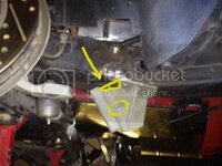
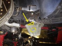
Ok, finally a little progress..... I welded the drver side stiffener in place (what Grampy described on the previous page, photo with the yellow markings).....

One more accomplishment is the center bracket:

319BDF84-2690-433E-946C-6F24EC81CB25-4230-0000048D5AFDF99A_zps2ef3ef77.jpg


.
For the fit-up it was easier to insert the bolts from the front, for the final install I need shorter 1/2" fine thread bolts....

Bump steer may not be perfect but should be waaay better than the stock setup and geometry.... I have to say: I don't drive like Grandma but I never really felt like the stock steering was all that bad, aside from the box being 30+ years old and worn.... I had more than 1" of free play in the steering wheel but bump steer I never felt was a big problem.... Maybe my steering was so ****** that I never realized.....lol

:lol:
 
Ok.... I realize now why the Steeroids kit uses three U-joints..... It is freakin tight with only two, the angle of the steering shaft is borderline, it's just a hair from binding the joints....

I do not like it !!!

The rack can't go a lot further towards the front, I need some room for the tie rods..... The tie rods fit barely between the A-arm and the rack as it is.....

There are options: the steering column shaft could be shortened; that would improve the angles of the U-joints..... Or....... I could give up and use three U- joints.....

I'll play with it some more but for now I really want to see more details from you guys who use only two joints.....
1) How far back from the front crossmember is your rack??
2) using a protractor (anglefinder), what's the angle from your steering column shaft to the doubleD shaft ??

Boy, I am glad this is not my daily driver.... It's on jackstands for two months now .... Lol
 
Ok.... I realize now why the Steeroids kit uses three U-joints..... It is freakin tight with only two, the angle of the steering shaft is borderline, it's just a hair from binding the joints....

I do not like it !!!

The rack can't go a lot further towards the front, I need some room for the tie rods..... The tie rods fit barely between the A-arm and the rack as it is.....

There are options: the steering column shaft could be shortened; that would improve the angles of the U-joints..... Or....... I could give up and use three U- joints.....

I'll play with it some more but for now I really want to see more details from you guys who use only two joints.....
1) How far back from the front crossmember is your rack??
2) using a protractor (anglefinder), what's the angle from your steering column shaft to the doubleD shaft ??

Boy, I am glad this is not my daily driver.... It's on jackstands for two months now .... Lol

Karsten, send me a email to make damn sure I don't miss this in the AM, and I will jack up the car, take measures, and show you my install, best as possible....

I don't have a lift, so maybe not the best pix around, but can give dimensions.....


I try to show a tape measure up there, but if not.....still say the positions best as I can describe....

:hi:
 
Back
Top