Old Project Revitalized - 56 Track Car

VetteMod - Corvette Restoration, Modding & Performance Forum

Help Support VetteMod Forum:

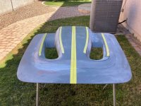
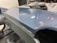
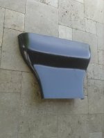
Here is another project moving along slowly. I am finishing the buck for my hood - working on symmetry and finish sanding. I will pull the carbon skin off the top of the buck to leave exposed carbon fiber on the bottom (underside of the hood) and will add one layer of fiberglass on top to serve as a "sanding surface" to prevent the CF from printing through the paint. Then I will bond the skin to the inner frame.

attachment.php
Hood 3.jpg
 
Last edited by a moderator:
Pappy -

Details as you have time - please. You said;
I will pull the carbon skin off the top of the buck...
Are you pulling a vacuum on the lower hood section with the CF - or doing all open layups?

The yellow tape is suspicious as if maybe doing a vacuum - that is why I ask.

Your skill with making these 2-part assemblies is very, very good. This hood will be awesome - and no weight at all. You are making me re-look at some of my pieces that are "dense" and thinking I need to revisit some. Thanks for the "challenge"!


Cheers - Jim
 
Pappy -

Details as you have time - please. You said;
I will pull the carbon skin off the top of the buck...
Are you pulling a vacuum on the lower hood section with the CF - or doing all open layups?

The yellow tape is suspicious as if maybe doing a vacuum - that is why I ask.

Your skill with making these 2-part assemblies is very, very good. This hood will be awesome - and no weight at all. You are making me re-look at some of my pieces that are "dense" and thinking I need to revisit some. Thanks for the "challenge"!


Cheers - Jim
Hey Jim,

I vacuum bag small, complex parts, but for the hood (and roof), I will do open lay-up using rollers and squeegees to clear any air bubbles and reduce the amount of resin in the finished product. It will be a little heavier than vacuum bagged, but not a lot. I use vinyl ester resin for the parts that have a fiberglass outer level for paint purposes. Epoxy resin does not work with fiberglass. I use epoxy for anything structural. The yellow tape you see is just to establish lines for symmetry measurements. Here are some photos of wet laid and vacuum bagged parts:

Brake Ducts Molds

attachment.php


Brake Duct Top wet laid before modifications (scoop for power steering air)

attachment.php


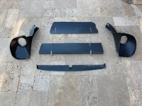
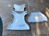
Panels behind the grill to complete a pre-radiator diffuser. They were all vacuum bagged. The small wing (in the middle) goes behind the grill center bar and may provide some downforce, but is mainly to divert more high pressure air up higher on the radiator.

attachment.php


I know BBShark won't like my thumbnails. If someone will tell me how to make the photos larger I will start doing that. ?Brake Duct Molds.jpgBrake Duct 3.jpgGrill 1.jpg
 
Last edited by a moderator:
I'm not sure how you are doing the pictures now but I make them bigger by saving the image address which looks like this (without the xxxx):

http://www.vettemod.com/forum/attachment.php?attachmentid=xxxxx

when you post a picture there is an image icon that looks like a yellow mountain picture. That will add


Or you can download the picture to "image hosting" in the top header.
 
those look great i have never done anything like that, i need tolearn how do do it becasue it looks fun
 
As an Amazon Associate we earn from qualifying purchases. Product prices and availability are accurate as of the date/time indicated and are subject to change.
A Viper track buddy of mine and I bought 6XD sequential transmissions at the same time. He has his on track (I still have a ways to go), and it works like a champ. We track at Inde in Wilcox Arizona, and last week he beat the NASA TTU track record by six seconds! Here is a video of the sequential in action you may like: [ame]https://www.youtube.com/watch?v=imifL0iQ1e0[/ame]
 
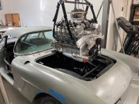
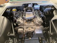
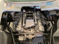
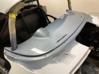
It fit. Also, notice the changes I am making to the roof - eliminated the 1" tall header stainless to try to cut down some drag.

attachment.php


attachment.php


attachment.php
Motor Install 10.jpgMotor Install 11.jpgMotor Install 13.jpg
 
wow wow wow....looks awesome

what exactly is the engine and components? did i miss that post?


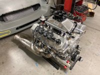
515 CI, big bore (4.6") short stroke (3.875"), 13:1 BBC. Hipped Brodix aluminum block and BB-3X heads. Callies ultra billet crank and rods, Comp Cams solid roller on roller cam bearings, T&D shaft rockers, Hogan sequential intake with 2200 cfm Wilson throttle body, Dan Olsen valve covers with spring oilers, Daily Signature billet dry sump pump and pan, Motec ECU.
 
wow wow wow....looks awesome

what exactly is the engine and components? did i miss that post?


515 CI, big bore (4.6") short stroke (3.875"), 13:1 BBC. Hipped Brodix aluminum block and BB-3X heads. Callies ultra billet crank and rods, Comp Cams solid roller on roller cam bearings, T&D shaft rockers, Hogan sequential intake with 2200 cfm Wilson throttle body, Dan Olsen valve covers with spring oilers, Daily Signature billet dry sump pump and pan, Motec ECU.

i need to add some WOWs!!! very nice
 
+ WOW! [How soon do we get to see it on the DYNO?]

Cheers - Jim

My MoTec tuner is working on calibrating the DBW throttle, and Brown and Miller is building oil and fuel lines as I send them specifications. Things move slow. The motor was on an engine dyno for break-in after it was built. Cutting it off early (6800 rpm) and with a fat AFR and only 34 degrees of timing, it made 852 hp and 685 ft/lbs torque. My tuner thinks it will eventually make closer to 900 hp, and that should be close to 800 whp. Probably enough.
 
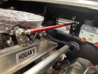
For those interested in converting a throttle body (or carb) to drive-by-wire, here is how the linkage from the BMW drive motor to the Wilson Dominator TB worked out. No slop and the throttle position indicators on the drive motor and TB stay in sync. I had to remove the throttle return spring from the primaries in the TB, but if you lose the linkage the MoTec ECU will shut the motor down if there is a discrepancy between the TPS's.

attachment.php
Throttle linkage 2.jpg
 

Attachments

  • Throttle linkage 2.jpg
    Throttle linkage 2.jpg
    87.3 KB
Last edited by a moderator:
Pappy -
Me likey! Offers a wider set of mounting options. One more thing I'll have to research (BMW - eh?) Source/PN as time permits. Thanks!

Cheers - Jim
 
Interesting. I the accelerator pedal w/ position sensor from a BMW also?
 
Painting the dash so I can put the windshield back on. It's a GM slate grey that looks more silver in some light, blue-grey in different light.
attachment.php
Dash Paint 1.jpgDash Paint 3.jpg
 
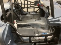
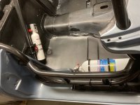
The forum has been slow lately, so I'll post up a couple of photos.. Time to start adding safety equipment - 10# Safecraft fire suppression system, 2.5# Safecraft fire extinguisher with Joe's Racing Products quick release, and a Safecraft FIA right side window net.

Fire Bottle.jpg]

attachment.php


attachment.php
Fire Bottle.jpgFire Bottle 2.jpg
 
Last edited by a moderator:
Wow it looks great. how much of a formal blue print or project plans do you have worked out for this project.
 
Wow it looks great. how much of a formal blue print or project plans do you have worked out for this project.

No blue print or project plans - mostly just evolution. I started with the NASA and SCCA rule books and worked toward compliance. Then the plan was: properly designed suspension, big power, big tires, big brakes, aft CG, and light weight. The "bigs" were in conflict with light weight. Then, aero came around - designed for 2-4 mile road courses with a top speed of 175 mph. Evolutionary improvements included changes to front and rear suspension components, aluminum motor for weight, MOTEC ECU for sequential injection in place of a carburetor, body mods to accommodate even larger tires, sequential transmission, and carbon fiber to reduce weight.
 
Back
Top