You are using an out of date browser. It may not display this or other websites correctly.
You should upgrade or use an alternative browser.
You should upgrade or use an alternative browser.
Internal Body Aerodynamics
- Thread starter vette427sbc
- Start date
Help Support VetteMod Forum:
phantomjock
Well-known member
rtj Thanks, that video is a good summary of radiator inlet strategy. It is easier to watch a video explanation, than read tons of documents. Here is a jump back to a distalation on 2 images that are germane: https://www.vettemod.com/threads/internal-body-aerodynamics.11568/post-131229
I have made a few mods to Walter Korpf's Figure 124 to show what is my approach. [Now, that the cat is out of the bag!] I've not included a splitter or air dam, but these belong as well. And - YES, I got to get going!!!

A few notes: the Kiwis are referring to the 1/3 opening - a good compromise. But closer to 1/6 is more optimum - if you don't have cooling challenges. Sealing around the radiator is important as they state, but I plan on supporting additional cooling with fans. This worked well on my SR. Adding "mechanical support" could be construed as an "unfair advantage" as some potentially additional downforce could be derived from this configuration, but I was never in a position to be challenged.
Regarding airflow separation in the duct. Duct design errors could be overcome with the fans. And, testing the entire upper lip could be tested in several configurations before setting one in fiberglass/CF. Basic design can build on diffuser knowledge, as there has been much testing on these in recent years. I like the hood fins SuperBuickGuy has incorporated on his build. These could be modified to help tailor airflow on exit (physically bent) or mechanically airspeed actuated, or via flow differential. [Any ARDUINO builders present?]
I hope the Kiwis are still at it. Unfortunately, the political situation "Downunder" has become a mess. I may not be returning anytime soon.
Cheers - Jim
With my radiator in a slant-forward position, the compromise to the duct length will be the average distance from inlet to radiator, or an "overbite configuration" - more to follow.
I have made a few mods to Walter Korpf's Figure 124 to show what is my approach. [Now, that the cat is out of the bag!] I've not included a splitter or air dam, but these belong as well. And - YES, I got to get going!!!
A few notes: the Kiwis are referring to the 1/3 opening - a good compromise. But closer to 1/6 is more optimum - if you don't have cooling challenges. Sealing around the radiator is important as they state, but I plan on supporting additional cooling with fans. This worked well on my SR. Adding "mechanical support" could be construed as an "unfair advantage" as some potentially additional downforce could be derived from this configuration, but I was never in a position to be challenged.
Regarding airflow separation in the duct. Duct design errors could be overcome with the fans. And, testing the entire upper lip could be tested in several configurations before setting one in fiberglass/CF. Basic design can build on diffuser knowledge, as there has been much testing on these in recent years. I like the hood fins SuperBuickGuy has incorporated on his build. These could be modified to help tailor airflow on exit (physically bent) or mechanically airspeed actuated, or via flow differential. [Any ARDUINO builders present?]
I hope the Kiwis are still at it. Unfortunately, the political situation "Downunder" has become a mess. I may not be returning anytime soon.
Cheers - Jim
With my radiator in a slant-forward position, the compromise to the duct length will be the average distance from inlet to radiator, or an "overbite configuration" - more to follow.
mfain
Well-known member
Interesting aero on the NASCAR Cup cars. Notice the splitter tunnels and the airflow out of the rear of the wheel wells. Belly pan under the motor. NACA duct, probably for cooling behind the motor. Rear diffuser.
phantomjock
Well-known member
Pappy-
A lot of interesting details there.
1. Guess it had some help getting inverted for our viewing...
2. Looks like damage to the center of the engine bay cover (looks bent) any thoughts?
3. Are the wheel flow fences asymmetric? Makes some sense in a roundy-round car or are we seeing damage there too?
4. Nice having the jack points built in the belly pan. I've made a note...
5. Drivers side tunnel looks like it feeds into a duct. Can you confirm - thoughts?
6. Interesting "air dam" in front of the drivers-side tire.
7. Reckon that is a side exhaust exit just aft of the wheel?
Some good information in that picture. I'd take some time to source the image, but it is nice outside and I've got some body work to get to.
Cheers - Jim


As an Amazon Associate we earn from qualifying purchases. Product prices and availability are accurate as of the date/time indicated and are subject to change.
mfain
Well-known member
Jim,
This was from a crash at the Coca Cola 600 last weekend - multiple roll-over so there is damage to the underside already. I think everything was pretty symmetrical before the crash. I was curious about the rear diffuser. I think at the leading edge, just forward of the rear tires, there is a "blow-out" panel that dumps the airflow from the diffuser when the car is traveling backwards - prevents lift like the roof flaps and keeps the car from going airborne backwards. If you google the crash there is video that may give you a better look.
Pappy
phantomjock
Well-known member
Pappy -
Thanks for the lead.
I did a bit of sleuthing and then an analysis of the accident frame by frame to get some good pics. Not the same car perhaps, but useful viewing of the belly pan.
I'll answer my own questions and add some pics and observations:
1. Guess it had some help getting inverted for our viewing... Hey it is NASCAR - Racing is Rubbing and sometimes a wheel folds up in the infield and oopsie - inverted!
2. Looks like damage to the center of the engine bay cover (looks bent) any thoughts? In the previous pic maybe so, but in the following still flat. Also note the diffuser segments are just inboard of the wheel/tire with the wheels straight. More on this later.

3. Are the wheel flow fences asymmetric? Makes some sense in a roundy-round car or are we seeing damage there too? No, they must have been damaged in the previous photo. Here they are clearly symmetrical. Also note the "skid" pucks fore and aft to minimize rubbing/wear on the fence. [Also note the pucks are venting smoke/heat from the engine bay. What goes out, most likely goes in. Are these the inlet cooling for the engine bay?

4. Nice having the jack points built in the belly pan. I've made a note... Yeah, I need those too.
5. Drivers side tunnel looks like it feeds into a duct. Can you confirm - thoughts? In the pics I pulled these appear to be closed. But Ducts could be useful in creating a double diffuser further aft.
6. Interesting "air dam" in front of the drivers-side tire. Shape is confirmed in these pics too. It also helps shape the diffuser into the wheel well space. So here is an idea; if the diffuser inboard of the wheel could create a high pressure area, just right for wheel brakes and bearings, and excess vented through louvers topside? Maybe, the increased in crosssectinal area as the diffuser slopes upward would cause the pressure rise and lower speed - hopefully to match the flow outside the wheel - or slightly higher pressure to push through the brakestack, rotor, and wheel.
7. Reckon that is a side exhaust exit just aft of the wheel? Could be. Earlier prototypes had the exhaust mid door, but drivers complained about cockpit heat, so maybe moved forward.
An interesting area seen on the passenger side wheel well. Intended opening to vent the wheel well - or damage? Can't tell.
Belly pan appears to have an upward slope (marked in yellow) then curves (recurves) to the section just behind the 2 "skid pucks." Or, is the shape just an illusion created by shadow in the video. Can't say.
One thing NASCAR has been working hard on; keeping the "Show" going. That means traffic, drafting, and "rubbing." So as a result, many aero enhancements are purposely limited. I.e., the splitter sizes are limited by rules, and underbody aero is being manipulated to ensure cars can draft and pass, something you could eliminate with some aerodynamic schemes. Similar situation in F1. Keep the cars tight for the show.
Last comment: From the departure of controlled racing (upright), until "proof of life," was a scant 31 seconds. Those are lonely moments sitting in the car waiting for the crash crew - even more so inverted. Glad everyone is good.

Cheers - Jim
Epoxy fairing compound is "going off" now. Sanding soon. Nose section.
Thanks for the lead.
I did a bit of sleuthing and then an analysis of the accident frame by frame to get some good pics. Not the same car perhaps, but useful viewing of the belly pan.
I'll answer my own questions and add some pics and observations:
1. Guess it had some help getting inverted for our viewing... Hey it is NASCAR - Racing is Rubbing and sometimes a wheel folds up in the infield and oopsie - inverted!
2. Looks like damage to the center of the engine bay cover (looks bent) any thoughts? In the previous pic maybe so, but in the following still flat. Also note the diffuser segments are just inboard of the wheel/tire with the wheels straight. More on this later.
3. Are the wheel flow fences asymmetric? Makes some sense in a roundy-round car or are we seeing damage there too? No, they must have been damaged in the previous photo. Here they are clearly symmetrical. Also note the "skid" pucks fore and aft to minimize rubbing/wear on the fence. [Also note the pucks are venting smoke/heat from the engine bay. What goes out, most likely goes in. Are these the inlet cooling for the engine bay?
4. Nice having the jack points built in the belly pan. I've made a note... Yeah, I need those too.
5. Drivers side tunnel looks like it feeds into a duct. Can you confirm - thoughts? In the pics I pulled these appear to be closed. But Ducts could be useful in creating a double diffuser further aft.
6. Interesting "air dam" in front of the drivers-side tire. Shape is confirmed in these pics too. It also helps shape the diffuser into the wheel well space. So here is an idea; if the diffuser inboard of the wheel could create a high pressure area, just right for wheel brakes and bearings, and excess vented through louvers topside? Maybe, the increased in crosssectinal area as the diffuser slopes upward would cause the pressure rise and lower speed - hopefully to match the flow outside the wheel - or slightly higher pressure to push through the brakestack, rotor, and wheel.
7. Reckon that is a side exhaust exit just aft of the wheel? Could be. Earlier prototypes had the exhaust mid door, but drivers complained about cockpit heat, so maybe moved forward.
An interesting area seen on the passenger side wheel well. Intended opening to vent the wheel well - or damage? Can't tell.
Belly pan appears to have an upward slope (marked in yellow) then curves (recurves) to the section just behind the 2 "skid pucks." Or, is the shape just an illusion created by shadow in the video. Can't say.
One thing NASCAR has been working hard on; keeping the "Show" going. That means traffic, drafting, and "rubbing." So as a result, many aero enhancements are purposely limited. I.e., the splitter sizes are limited by rules, and underbody aero is being manipulated to ensure cars can draft and pass, something you could eliminate with some aerodynamic schemes. Similar situation in F1. Keep the cars tight for the show.
Last comment: From the departure of controlled racing (upright), until "proof of life," was a scant 31 seconds. Those are lonely moments sitting in the car waiting for the crash crew - even more so inverted. Glad everyone is good.
Cheers - Jim
Epoxy fairing compound is "going off" now. Sanding soon. Nose section.
Last edited:
That was really informative and kinda entertaining. The on track "oops" at the end was a nice touch.
rtj
Well-known member
- Joined
- Nov 5, 2011
- Messages
- 3,598
- Reaction score
- 211
Fan cars still work.
https://evo.co.uk/electric-cars/204...-fan-car-claims-goodwood-fos-hillclimb-record
“Other challenges of the system still to be resolved include creating an effective filter system so that following cars aren’t peppered with debris that’s sucked up and ejected, but there’s then the issue of what to do with debris that is filtered out. You don’t want to be carrying it around and emptying bags when you pop the car on charge like it’s an expensive vacuum cleaner.”
phantomjock
Well-known member
Found a real nice playlist of Aero Analysis on the Bugatti Boldie. Nice what you can do when starting with a blank sheet of paper - but there are a few items that can be incorporated into a resto/mod of a C3 too. This is something that rtj would normally bring in - but I couldn't resist. [I don't think this is a double posting - I could be wrong].]
There are some interesting F1 clips that cover belly pan aero worthy of mention too.
Cheers - Jim
There are some interesting F1 clips that cover belly pan aero worthy of mention too.
Cheers - Jim
mfain
Well-known member
Here is a real-world vortex visualization that is kind of interesting. It appears that the canards are creating a low pressure area (vortex) near the top/outside of the front wheel and is pulling air out of the wheel well (or perhaps out of the wheel between the barrel and brake rotor - a very narrow area). Judging from the brake lights he is on the brakes so there may be an element of steam in the water vapor making it easier to see. The discharge from the open fender vent is not nearly as significant.

phantomjock
Well-known member
Pappy -
Thanks for bringing that in. A lot going on there. Do you know this particular car?
Areas I'm looking at:

FRONT:
MID-SECTION/UNDERBODY:
FRONT:
Great analysis on the front wheel flows. I can't tell if the flow you can see over the hood is on the hood or the fender. It definitely looks as if it is from the louvers. The pronounced "roll-off" from fender to hood makes either possible. Have you had a similar view in the rain in your viper? Unfortunately, we can't see any pressure build up ahead of the front wheels/bumper as the water is still on the pavement. If drafting another car - maybe.
I suspect this a newer version Viper. I guess the side vents are a give-away [like on a C-3 - or a "port hole" Buick]. For the side fender vents a Red Car might show better contrast - if there is flow. NOTE-2-SELF Michael Keaton in Night Shift : Add Plastic-Dip Rattle Can - to Track Test Kit!
MID-SECTION:
I note the underbody "shredding." As a newer version Viper there is a belly pan (confirmation?):

Also the Front Splitter (with diffusers) make for a clean entry:

The engine bay for the Viper has an After-Market product worthy of copying. Placement of the NACA Ducts for a C-3 is something to consider. (Although, I suspect this Viper doesn't have one of these and most likely is an open engine bay, hence the separation/shredding - but then again, water is heavier than air):

REAR:
Rear wheel flow shows the "over top" as the front and could well do with an "exit." Any rear louvers on Vipers? Adding an "air curtain" ahead of the rear wheels would most likely be useful here.
The rear diffuser looks to be doing its job.
Thanks again Pappy. Wet water testing is better/cleaner than sand or flour - easier to wipe down. Wish we had some Wing-Flow to look at too. Maybe next time.
Cheers - Jim
Florida Tags?
Thanks for bringing that in. A lot going on there. Do you know this particular car?
Areas I'm looking at:
FRONT:
Front wheel -- vortex and Fender Louvers
Hood
Fender Side Vent (Disappointing)
MID-SECTION/UNDERBODY:
Belly Pan, etc.
REAR:Rear Wheel
Diffuser
Rear Flow
FRONT:
Great analysis on the front wheel flows. I can't tell if the flow you can see over the hood is on the hood or the fender. It definitely looks as if it is from the louvers. The pronounced "roll-off" from fender to hood makes either possible. Have you had a similar view in the rain in your viper? Unfortunately, we can't see any pressure build up ahead of the front wheels/bumper as the water is still on the pavement. If drafting another car - maybe.
I suspect this a newer version Viper. I guess the side vents are a give-away [like on a C-3 - or a "port hole" Buick]. For the side fender vents a Red Car might show better contrast - if there is flow. NOTE-2-SELF Michael Keaton in Night Shift : Add Plastic-Dip Rattle Can - to Track Test Kit!
MID-SECTION:
I note the underbody "shredding." As a newer version Viper there is a belly pan (confirmation?):
Also the Front Splitter (with diffusers) make for a clean entry:
The engine bay for the Viper has an After-Market product worthy of copying. Placement of the NACA Ducts for a C-3 is something to consider. (Although, I suspect this Viper doesn't have one of these and most likely is an open engine bay, hence the separation/shredding - but then again, water is heavier than air):
REAR:
Rear wheel flow shows the "over top" as the front and could well do with an "exit." Any rear louvers on Vipers? Adding an "air curtain" ahead of the rear wheels would most likely be useful here.
The rear diffuser looks to be doing its job.
Thanks again Pappy. Wet water testing is better/cleaner than sand or flour - easier to wipe down. Wish we had some Wing-Flow to look at too. Maybe next time.
Cheers - Jim
Florida Tags?
mfain
Well-known member
Hey Jim,Pappy -
Thanks for bringing that in. A lot going on there. Do you know this particular car?
Areas I'm looking at:
View attachment 53931
FRONT:
Front wheel -- vortex and Fender LouversHoodFender Side Vent (Disappointing)
MID-SECTION/UNDERBODY:
Belly Pan, etc.REAR:
Rear WheelDiffuserRear Flow
FRONT:
Great analysis on the front wheel flows. I can't tell if the flow you can see over the hood is on the hood or the fender. It definitely looks as if it is from the louvers. The pronounced "roll-off" from fender to hood makes either possible. Have you had a similar view in the rain in your viper? Unfortunately, we can't see any pressure build up ahead of the front wheels/bumper as the water is still on the pavement. If drafting another car - maybe.
I suspect this a newer version Viper. I guess the side vents are a give-away [like on a C-3 - or a "port hole" Buick]. For the side fender vents a Red Car might show better contrast - if there is flow. NOTE-2-SELF Michael Keaton in Night Shift : Add Plastic-Dip Rattle Can - to Track Test Kit!
MID-SECTION:
I note the underbody "shredding." As a newer version Viper there is a belly pan (confirmation?):
View attachment 53928
Also the Front Splitter (with diffusers) make for a clean entry:
View attachment 53929
The engine bay for the Viper has an After-Market product worthy of copying. Placement of the NACA Ducts for a C-3 is something to consider. (Although, I suspect this Viper doesn't have one of these and most likely is an open engine bay, hence the separation/shredding - but then again, water is heavier than air):
View attachment 53930
REAR:
Rear wheel flow shows the "over top" as the front and could well do with an "exit." Any rear louvers on Vipers? Adding an "air curtain" ahead of the rear wheels would most likely be useful here.
The rear diffuser looks to be doing its job.
Thanks again Pappy. Wet water testing is better/cleaner than sand or flour - easier to wipe down. Wish we had some Wing-Flow to look at too. Maybe next time.
Cheers - Jim
Florida Tags?
This is a stock Gen V ACR-E, identical to mine except for the stripes. It belonged to William Hubble, owner of Hubble Racing in South Florida. He died in Feb at an early age of Parkinson's. He had 2 IMSA GTP Corvettes and a couple of Lambo race cars. It does have a full belly pan as depicted in your photos. I have never tracked my car in the rain (dry slicks LOL), but I do get a lot of dry debris up and out of the fender openings - rubber, rocks, dirt, small children, etc. I think most of the debris is being thrown out by the rotating wheel and not by any low pressure area created by the opening. It needs a raised lip in front of the vent to create a pocket of low pressure behind it. Yarn strings show an upward flow, but with the factory louvers installed, there is no movement of air out of the wheel well through the vents. The front splitter and undertray are very effective. The ACR-E has an extended, replaceable forward splitter. A comment on the side vents - They have a fair sized, but cluttered opening into the engine bay, but because of the front undertray there would be no water vapor that would be visible exiting the side vent in this photo.


phantomjock
Well-known member
Pappy -
Thanks for those pics.
Looks like Dodge used a lot of the Aero-Precious real estate for climate control and other nice items. I bet there are some sweet ideas for underhood ventilation to fender vent if you wanted to do some Time-Attack!
Right now I am focusing on Diffuser-Science this week, as the rain has set in (Florida has its days), and the rear end is the next big glass layup. Sorting curves, percent of overall length, h/d, ease of build, curvature, blades, orientation, efficiency, adjust ability, etc, etc..
Yes - yes - pics soon. Also, working the boat, and that will be a big interruption for the end of July and early August.
Meanwhile keep thinking; C3/IMSA GTP Corvette mash-up. Kinda' like in my sig below.
Cheers - Jim
mfain
Well-known member
Most of the underhood venting is done through the six hood vents and probably contributes to aero by directing the airflow up and over, and around the roof. The screens in the hood vents are removed for track duty. If you look at a lot of the exotics they tend to route air out the back of the wheel well through side vents (rather than out of the engine compartment or front bay) for aero. Even the new NASCAR Cup car uses the front of the side skirts to turn inward behind the front tire (forming barge boards) to direct airflow outboard of the skirts - I presume to form an air curtain ahead of the rear tires which now have slight fender flares. On my '56 I am using duct work from the radiator to vent air out of chimney openings in the hood. Then I am using sort-of barge boards along the frame rails to direct air into the two diffuser tunnels I have between the frame rail and the outer body sill (about a foot wide). I put small lips in front of my side coves to help draw air out there - the right side is open to the area where the dry sump tank fits, and the other side is the exit for oil cooler discharge air.Pappy -
Thanks for those pics.
Looks like Dodge used a lot of the Aero-Precious real estate for climate control and other nice items. I bet there are some sweet ideas for underhood ventilation to fender vent if you wanted to do some Time-Attack!
Right now I am focusing on Diffuser-Science this week, as the rain has set in (Florida has its days), and the rear end is the next big glass layup. Sorting curves, percent of overall length, h/d, ease of build, curvature, blades, orientation, efficiency, adjust ability, etc, etc..
Yes - yes - pics soon. Also, working the boat, and that will be a big interruption for the end of July and early August.
Meanwhile keep thinking; C3/IMSA GTP Corvette mash-up. Kinda' like in my sig below.
Cheers - Jim

phantomjock
Well-known member
Pappy - Looking forward to seeing those. I'm on a slightly similar path and have shaped the upper surface, and the side walls. But, alas - rain so "glassin' the lower surfaces [of a sellig 1223 section] waits. Not just Tunnels - but an homage to the Lotus 78/79.... Then I am using sort-of barge boards along the frame rails to direct air into the two diffuser tunnels I have between the frame rail and the outer body sill (about a foot wide). I put small lips in front of my side coves to help draw air out there - the right side is open to the area where the dry sump tank fits, and the other side is the exit for oil cooler discharge air.
Cheers - Jim
rtj
Well-known member
- Joined
- Nov 5, 2011
- Messages
- 3,598
- Reaction score
- 211
SuperBuickGuy
Well-known member
a wing commercial, but no real data.
rtj
Well-known member
- Joined
- Nov 5, 2011
- Messages
- 3,598
- Reaction score
- 211
I haven’t had a chance to go though this, but there appears to be a lot of info.
I saw an ad for corvette parts and he was selling a wing.
https://9livesracing.com/pages/cfd-testing
Edit: he seems to cater to the import cars.
I saw an ad for corvette parts and he was selling a wing.
https://9livesracing.com/pages/cfd-testing
Edit: he seems to cater to the import cars.
Last edited:
rtj
Well-known member
- Joined
- Nov 5, 2011
- Messages
- 3,598
- Reaction score
- 211
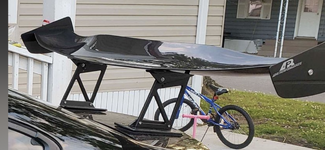
I was looking around and saw several APR 200 and 300 wings within a few hours at roughly 1/2 price.
It turns out young guys are dressing up their cars with them and when they sell the car or just get tired of the look they sell them cheap.
So, if you want to experiment with wings, that would be cost effective.
I’ll probably wait for a HP upgrade before adding with a wing.
It turns out young guys are dressing up their cars with them and when they sell the car or just get tired of the look they sell them cheap.
So, if you want to experiment with wings, that would be cost effective.
I’ll probably wait for a HP upgrade before adding with a wing.
mfain
Well-known member
This video (around the 24-minute mark) has some interesting aerodynamic discussions regarding the C8Z06 aero, especially regarding the underbelly strakes.
https://www.corvetteforum.com/forum...cussion/4676116-savagegeese-video-review.html
https://www.corvetteforum.com/forum...cussion/4676116-savagegeese-video-review.html
Similar threads
- Replies
- 3
- Views
- 1K
- Replies
- 93
- Views
- 22K
- Replies
- 31
- Views
- 10K