I saw this build and was amazed at the meticulous and well thought out process of Restomodding an XKE. This is the best documented build of any car I have ever seen. More to come!
Owner: Ken Hiebert
City: Toronto, Canada
Car Model: 1965 Jaguar E-Type FHC
Engine: 2002 GM LS1 V8
Cooling: Afco dual pass aluminum radiator
Exhaust: Dual 2 1/2" into one 3" Magnaflow muffler into two 2 1/2" Vibrant resonators
Transmission: Tremac 6 speed
Rear Axle: Salisbury 3.54:1 with Powerloc limited slip differential
Front Susp.: Fast Cars Inc. IFS
Rear Susp.: Modified Jaguar E-Type IRS
Brakes: Wilwood all around
Wheels/Tires: Americain Racing Classic 100 wheels with 245/45/17 front and 275/40/17 rear tires
Body Mods: Bumper delete
Interior: Mazda Miata seats, Vintage Air A/C
Electrical: Modified GM harness using all Delphi Metri-Pack connectors
This project is to create a restomod of a 1965 Jaguar E-Type FHC, (fixed head coupe). A restomod combines the performance, comforts and reliability of a modern car while retaining most of the appearance of the original car. Just my style, my passion.
I'm starting out with a very rough, original car, no engine, no transmission, a good candidate for this project. The car came with a dilapidated white Series II bonnet which can be seen in the purchase photos of the car and it also came with the original Series I bonnet. These photos I took when I viewed the car for the first time:


My inspiration for this project comes from a few Jaguars already on the road. One of my favorites is Larry Ligas' full race car from Predator Performance Racing Inc. of Largo, Florida. That was listed for sale on Fantasy Junction, brokers of fine collector automobiles and vintage race cars.
[www.fantasyjunction.com]
It is pictured here:


The car in my project, which I hope to finish one day, will not be a full race car, but will be driven and driven hard. Touring, autocrossing and the occasional track days will be it's duties.
I hope you find some interest and entertainment in this adventure.
One of the first purchases I made for this car was the engine and transmission package. This was shipped up to Niagara Falls, N.Y. from a dealer in Philidelphia. I rented a truck and brought my baby home.

Frame Table:

Construction begins:
With the chassis table leveled and squared, the first step in building the frame is establishing my ride height. This is calculated using the amount of suspension travel I want and where I want the wheels in the wheel wells. Everything on this car hinged on the bonnet height. I made the bonnet as low as I could and still have 3" of suspension travel. From there, I knew where the body would sit and where the IRS would sit, all at normal ride height. I figured building the frame rails 3" above my chassis table would give me good working room. It ended up, the front crossmember would be 3 3/4" above the table and the differential, 4 1/8" above the table. Then it was all a matter of placing them center on the table and at the established 96" wheel base. I welded lengths of angle iron under the exact wheel base lines, marked my hub to hub lines on them using a plumb bob, checked my 96" wheel base and checked corner to corner for square.


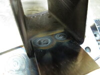
With the differential sitting on the chassis table, I now needed to fabricate mounts for it. The upper mount would be poly bushed, bolted to an assembly of three 2"x2" tubes, what I call, the rear crossmember.
Diff mount


Frame Rails:
Tying the front and rear suspensions together will be done with perimeter frame rails. The E-Type has large 7" high body sills which gave the original monocoque body it's strength. I'll be running my frame rails through them. I ran the 2x3" rails mid-height in the sill and ran a secondary shaped tube below it to join the bottom part of the outer sill and the floor together.
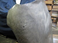
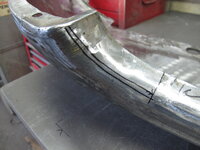
The lower shaped tube is 2x2"x .065 with a 1" corner cut from it. I did the cut in several sections but it still had to be straightened.
Tacked it to heavy angle iron:


Next will be IRS upgrades.
P.S. I'm loving my chassis table so much, I gave'er a coat of paint.
Watts Linkage:
Under hard acceleration, the Jaguar IRS can experience wheel hop due to the lower control arm flexing. I'm going to try and lessen that by adding a watts linkage to the rear hub and I'll widen the spacing of the rear springs.
Modified rear hub

To complete the watts linkage, I need to install the four attachment points for the heim joints on the frame. Those will come later.
Lower Control Arms
These, on the Jaguar IRS, do too many things. One thing you don't want them to do is twist. Under heavy acceleration or hard braking load, they do. To help lessen this, I picked up on a theory from a post on the Independent Rear Suspension Forum. In the first post of the thread, "Ralphy" states "The further outboard you mount the coilovers, the better. In the third and fourth post, "Tyrellracing" talks about a FINITE ELEMENT ANALYSIS done to show that the arrangement of the coilovers further apart, would give them a greater ability to act as a TORQUE COUPLE and resist rotation while supporting the weight.
I liked the theory, right or wrong, and implemented it on my lower control arms.
Widened the coilover spacing by a total of 3 1/4", (my width was limited by the placement of the fuel tank in the car):
Modified control arms

To be continued...........
Owner: Ken Hiebert
City: Toronto, Canada
Car Model: 1965 Jaguar E-Type FHC
Engine: 2002 GM LS1 V8
Cooling: Afco dual pass aluminum radiator
Exhaust: Dual 2 1/2" into one 3" Magnaflow muffler into two 2 1/2" Vibrant resonators
Transmission: Tremac 6 speed
Rear Axle: Salisbury 3.54:1 with Powerloc limited slip differential
Front Susp.: Fast Cars Inc. IFS
Rear Susp.: Modified Jaguar E-Type IRS
Brakes: Wilwood all around
Wheels/Tires: Americain Racing Classic 100 wheels with 245/45/17 front and 275/40/17 rear tires
Body Mods: Bumper delete
Interior: Mazda Miata seats, Vintage Air A/C
Electrical: Modified GM harness using all Delphi Metri-Pack connectors
This project is to create a restomod of a 1965 Jaguar E-Type FHC, (fixed head coupe). A restomod combines the performance, comforts and reliability of a modern car while retaining most of the appearance of the original car. Just my style, my passion.
I'm starting out with a very rough, original car, no engine, no transmission, a good candidate for this project. The car came with a dilapidated white Series II bonnet which can be seen in the purchase photos of the car and it also came with the original Series I bonnet. These photos I took when I viewed the car for the first time:
My inspiration for this project comes from a few Jaguars already on the road. One of my favorites is Larry Ligas' full race car from Predator Performance Racing Inc. of Largo, Florida. That was listed for sale on Fantasy Junction, brokers of fine collector automobiles and vintage race cars.
[www.fantasyjunction.com]
It is pictured here:
The car in my project, which I hope to finish one day, will not be a full race car, but will be driven and driven hard. Touring, autocrossing and the occasional track days will be it's duties.
I hope you find some interest and entertainment in this adventure.
One of the first purchases I made for this car was the engine and transmission package. This was shipped up to Niagara Falls, N.Y. from a dealer in Philidelphia. I rented a truck and brought my baby home.
Frame Table:
Construction begins:
With the chassis table leveled and squared, the first step in building the frame is establishing my ride height. This is calculated using the amount of suspension travel I want and where I want the wheels in the wheel wells. Everything on this car hinged on the bonnet height. I made the bonnet as low as I could and still have 3" of suspension travel. From there, I knew where the body would sit and where the IRS would sit, all at normal ride height. I figured building the frame rails 3" above my chassis table would give me good working room. It ended up, the front crossmember would be 3 3/4" above the table and the differential, 4 1/8" above the table. Then it was all a matter of placing them center on the table and at the established 96" wheel base. I welded lengths of angle iron under the exact wheel base lines, marked my hub to hub lines on them using a plumb bob, checked my 96" wheel base and checked corner to corner for square.
With the differential sitting on the chassis table, I now needed to fabricate mounts for it. The upper mount would be poly bushed, bolted to an assembly of three 2"x2" tubes, what I call, the rear crossmember.
Diff mount
Frame Rails:
Tying the front and rear suspensions together will be done with perimeter frame rails. The E-Type has large 7" high body sills which gave the original monocoque body it's strength. I'll be running my frame rails through them. I ran the 2x3" rails mid-height in the sill and ran a secondary shaped tube below it to join the bottom part of the outer sill and the floor together.
The lower shaped tube is 2x2"x .065 with a 1" corner cut from it. I did the cut in several sections but it still had to be straightened.
Tacked it to heavy angle iron:
Next will be IRS upgrades.
P.S. I'm loving my chassis table so much, I gave'er a coat of paint.
Watts Linkage:
Under hard acceleration, the Jaguar IRS can experience wheel hop due to the lower control arm flexing. I'm going to try and lessen that by adding a watts linkage to the rear hub and I'll widen the spacing of the rear springs.
Modified rear hub
To complete the watts linkage, I need to install the four attachment points for the heim joints on the frame. Those will come later.
Lower Control Arms
These, on the Jaguar IRS, do too many things. One thing you don't want them to do is twist. Under heavy acceleration or hard braking load, they do. To help lessen this, I picked up on a theory from a post on the Independent Rear Suspension Forum. In the first post of the thread, "Ralphy" states "The further outboard you mount the coilovers, the better. In the third and fourth post, "Tyrellracing" talks about a FINITE ELEMENT ANALYSIS done to show that the arrangement of the coilovers further apart, would give them a greater ability to act as a TORQUE COUPLE and resist rotation while supporting the weight.
I liked the theory, right or wrong, and implemented it on my lower control arms.
Widened the coilover spacing by a total of 3 1/4", (my width was limited by the placement of the fuel tank in the car):
Modified control arms
To be continued...........


.JPG")