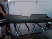
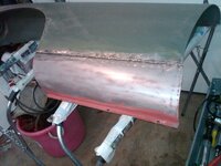
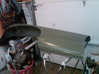
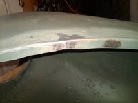
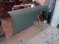
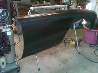
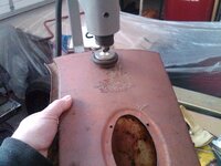
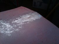
1958 MGA Coupe

VetteMod - Corvette Restoration, Modding & Performance Forum

Help Support VetteMod Forum:

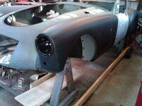
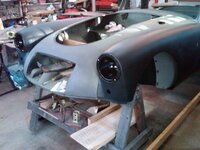
[FS]1958 MGA Coupe, fully restored, 60% Steel, 40% Weld.:rofl:
More seriously, nice job.
 
[FS]1958 MGA Coupe, fully restored, 60% Steel, 40% Weld.:rofl:
More seriously, nice job.
you have that backwards.....60% weld 40% steel

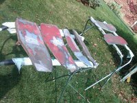
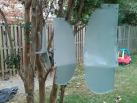
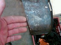
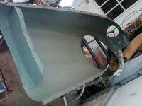
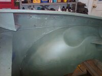
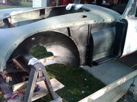
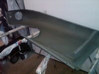
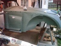
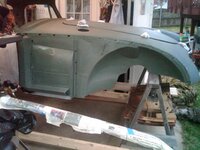
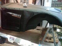
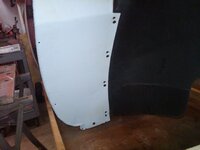
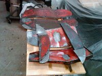
Jasco prep and prime on inner fender splash guards
IMG04758-20141029-2125_zps8bd09343.jpg

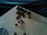
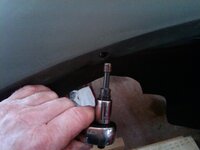
and tapped the shut face panel screws, Neil helped me out with the correct size screw

IMG04759-20141029-2129_zpsa14f79a3.jpg
 
moving forward to finishing those damn inner fenders....they are like work!!!

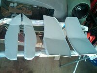
i rinsed off the jasco as per the directions then sanded the pieces again and applied some fiberglass short strand body filler to my weld seams sanded quickly and primed one side of them.
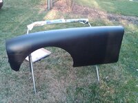
the only thing i dont like about the jasco is that you have to rinse it with water, it just rubs me the wrong way to use water on bare steel., although we do wet sand primer.....

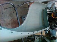
these inner fenders are being brought up to a presentable level so that the final paint is smooth on them i am not worrying about perfection on these.

IMG04761-20141030-1331_zpsa5cce34c.jpg

IMG04764-20141030-1342_zps93c9f449.jpg

IMG04767-20141030-1344_zpsd605fe12.jpg
 
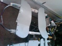
inners fenders are done....they came out pretty nice for panels that you will never see. now to move on to the shut face panels

IMG04770-20141031-1317_zpsbd5c5558.jpg
 
well today had to turn the heat on in the garage for the newly painted stuff to dry, primers can take a long time at 60* to dry.

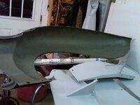
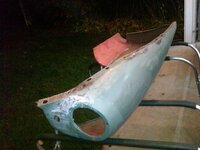
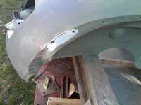
primed the inside of the right rear fender

IMG04782-20141101-2203_zps6a331ae0.jpg

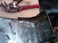
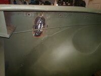
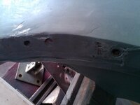
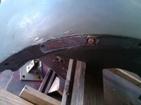
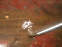
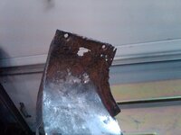
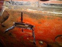
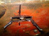
can you see the red paint buried in that crevice.....I believe that is original paint and the shut face panel was mashed into place and it created that dent.
IMG04783-20141101-2231_zpscb7286ab.jpg

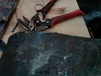
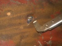
its the shiny raised part which is out of focus by the snips
IMG04784-20141101-2231_zps34031706.jpg

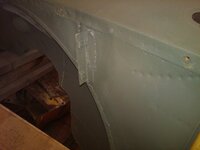
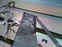
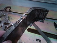
and my solution is to relieve the crunched part to make it fit better. iwill weld it back together after some more fitting. you cant be scared to cut stuff to make it fit better in projects like this

IMG04785-20141101-2234_zps24952615.jpg
 
so part of the process of filling time is to mock up everything in final form and then take it all apart again. it feels really good to have something actually put back together on the body

so all the bolts get chased with a thread cleaner and all the washers get hit with the grinder

IMG04786-20141102-1029_zps5ae3406a.jpg

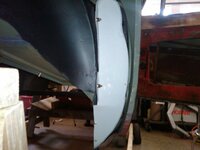
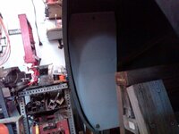
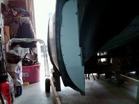
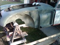
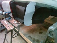
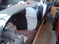
and we have a fully installed fender with spashguards all the bolts in place and tight


IMG04792-20141102-1124_zps16fe79bf.jpg

IMG04787-20141102-1123_zps1fcb989e.jpg

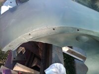
nice and tight screw holes

IMG04795-20141102-1253_zps8a6660a9.jpg
IMG04793-20141102-1125_zpsf252405f.jpg
IMG04798-20141102-1341_zpse0b9c608.jpg

IMG04801-20141102-1606_zps0aed1d09.jpg
 
As an Amazon Associate we earn from qualifying purchases. Product prices and availability are accurate as of the date/time indicated and are subject to change.
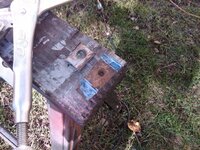
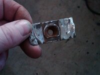
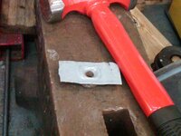
several easy tasks.....weld in nut for the fender bolt, attach and weld in rear spalsh guard tab, sand inner fender one more time and prime

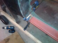
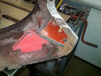
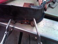
some times theres no easy way to get a good clamp, so this gave me an easy quick hold for a few smalls tacks then i could weld the rest from the back

IMG04802-20141103-1223_zps6f101fa8.jpg

IMG04803-20141103-1307_zpsc01210ef.jpg
 
continuing on with the labor of love...full dress rehearsal on drivers side rear fender and two splash guards

all bolts in place and operational, i had to weld the other front fender nut into the body panel piece behind the door latch pillars, not hard just work since i had to cut it out of a piece of the old front part of the car.

IMG04805-20141104-1333_zpsc94d14c7.jpg

IMG04809-20141104-1334_zpsb055d271.jpg

IMG04808-20141104-1334_zps743f0f91.jpg

the splash guards will get the hole drilled when i have the actual rubber piece that attaches to them.
 
It probably goes without saying, but your patience and attention to detail is an inspiration to us all. Keep up the good work! :-)
 
thks red77

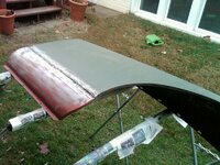
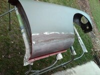
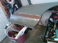
easy 90 mins or so found a few more pin holes in fender that needed some mending and then once again sand and wipe down with wax and degreaser and then prime, I had wanted to get the out side of the fender where the patch panel is sanded and primed but its hard to work on both sides of a panel at once so tonight was just devoted to the inner fender and outside by the fender mounting holes

IMG04817-20141106-2052_zps5520ee55.jpg

IMG04821-20141106-2120_zps6a4348a6.jpg

IMG04820-20141106-2118_zps686ae7d7.jpg

IMG04819-20141106-2117_zps4321c7ba.jpg


I am excited because I actually see an end to using the green self etching primer in the near future, one more inner fender and then the 2 doors so maybe 2 more cans, maybe 3 just to be safe.
 
thks

sand the red primer off , hit the open lap area with a wire brush and then 36 grit and use short strand fiberglass to fill the gap and prime the fender this is just to move it to the next phase, if its not raining tomorrow it will get a quick sanding and black primer.


IMG04824-20141116-1626_zps1fd7202c.jpg

IMG04825-20141116-1655_zps103eda75.jpg
 
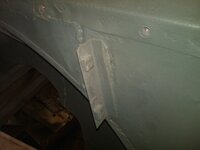
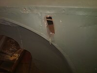
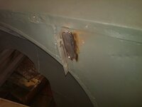
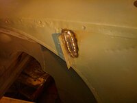
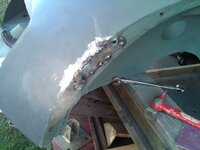
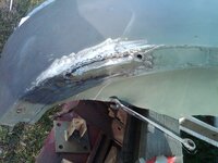
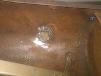
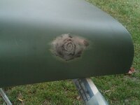
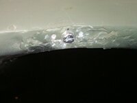
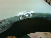
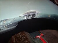
two more weld repairs, a tear in the fender lip and a rust spot on the inner splash guard mounting tab

IMG04827-20141117-1358_zpsf6df83ac.jpg

this has to go the spot that is bubbling if you ignore bubbling spots you are just fooling your self

IMG04828-20141117-1358_zps285be5bf.jpg
IMG04829-20141117-1419_zps005586f1.jpg

IMG04830-20141117-1433_zps14af44f5.jpg

IMG04831-20141117-1449_zpse5199a9e.jpg

IMG04834-20141117-1502_zps5c7cd094.jpg

added some body filler to low spots and prime it

IMG04835-20141117-1524_zps8aadbbc7.jpg

IMG04836-20141117-1525_zps6a4b3055.jpg
 
nice day outside so lets use the temps to our advantage

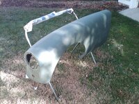
one green primed fender to Black primed

IMG04862-20141130-1317_zpsdb5024ab.jpg

IMG04874-20141130-1522_zpsfdfc7b8f.jpg

and I eye balled some more rust spots I didn't like

IMG04864-20141130-1329_zps27d60d5f.jpg

so I cut the out side piece all the way off and wire brushed the inner panel and use self etching weld through primer
IMG04865-20141130-1402_zpsc402f440.jpg

make a piece to fill the void

IMG04866-20141130-1426_zpsee477b18.jpg

IMG04867-20141130-1427_zps4b70e1c7.jpg

tack in place

IMG04868-20141130-1442_zps0a22af2f.jpg

grind away

IMG04869-20141130-1446_zps48ac56ff.jpg

no more rust holes and ready to move to the next phase

IMG04870-20141130-1503_zps8ecc5085.jpg

no more things to do on inner fender so move to black primer, well after the primer dries for a day or two I will put seam sealer on all the weld seams. I also will make the inner sill cap ends and pop rivet them in place so they can be removed if necessary for inspection at a later date

IMG04871-20141130-1504_zps165b01cf.jpg

IMG04872-20141130-1511_zpsbbce27ce.jpg
 
thks

and we move to the last fender....i am running out of warm weather to do this outside, i still have to prime the inside of the fender and then can move the fender to the "black primer" phase.

IMG04876-20141203-1255_zpse5456ac5.jpg

IMG04877-20141203-1313_zps10c4d3e3.jpg

IMG04878-20141203-1322_zpsb0e3d4a0.jpg
 
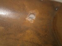
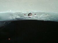
the front mirrors are over the front wheels , but I have one too many holes and will have to weld one of them up and weld up a radio antenna hole

IMG04885-20141206-1309_zps2460e51d.jpg

IMG04886-20141206-1311_zps420e3e1d.jpg

the copper backing plate

IMG04887-20141206-1311_zps6beb9bf0.jpg

the radio antenna hole

IMG04888-20141206-1316_zpse6b7fb21.jpg

IMG04889-20141206-1327_zpsfa428867.jpg

IMG04890-20141206-1342_zpsb939b983.jpg

front mirror hole and the one I filled in
IMG04891-20141206-1342_zps41736e18.jpg

all pin holes welded up and inner fender sanded

IMG04892-20141206-1425_zps21fa936b.jpg
IMG04894-20141206-1445_zpsb31b8b0e.jpg

time to take a break for lunch and let the primer dry
back from lunch....

add a little body filler to where the repair was made from the radio antenna lead
IMG04895-20141206-1559_zps5fd0cc02.jpg

primed since there was some shiny metal showing
IMG04896-20141206-1600_zpsd88e2068.jpg

primed in black meaning nothing left to do

IMG04897-20141206-1606_zps68f78267.jpg

wiped down fender with a wax and degreaser and move to the black primer stage

IMG04898-20141206-1616_zps41c98388.jpg

IMG04899-20141206-1624_zps9fcb5b3c.jpg
 
Last edited:
lets add another fender nut that is missing and build up a low spot

IMG04900-20141207-1250_zps2aefc7d1.jpg

IMG04901-20141207-1255_zps3607c74f.jpg

IMG04903-20141207-1302_zps3b53c402.jpg

IMG04907-20141207-1335_zps27df257c.jpg

IMG04910-20141207-1337_zpsc364de99.jpg

IMG04913-20141207-1404_zps2cd10ed9.jpg

hold in place to plug weld

IMG04914-20141207-1436_zps58abd971.jpg

see the low spot in the curve

IMG04916-20141207-1452_zps00c95e3c.jpg

so lets add some 16 ga to build it up
IMG04917-20141207-1528_zpsc212afd1.jpg

IMG04918-20141207-1542_zps4c25f327.jpg


IMG04919-20141207-1543_zpse9c3d6e2.jpg

IMG04920-20141207-1551_zps9e71902c.jpg


all contact points have to be metal to metal, no filler in compression areas, but filler can be next to them

IMG04921-20141207-1600_zps82e3a48f.jpg
 
Last edited:
well somehow 2 weeks ago I hurt my back doing pretty much nothing????? so its been slow for me since then but today I went back at it , kind of light but any way...the task is to fully model the pass side front fender and inner splash guard
give a quick sand to the body filler and prime it

IMG04925-20141219-1526_zpsf380ebde.jpg


who would have thought that the inner fender splash guard holes would not be universal to all MGA's? since my inner fenders are off of a newer model the caged nuts are in slightly different locations......this is why you test fit everything before final painting

IMG04926-20141219-1636_zps73a5d4fb.jpg

IMG04927-20141219-1654_zps1573a142.jpg
 
todays chore is to mount the drivers side fender and inner fender and use all bolts and fully "model" the fit

chase all the holes and bolts
IMG04931-20141220-1215_zps16871e3a.jpg


it may be a combination of adjusting all the holes not just the bottom ones....I will look at that again tomorrow

IMG04933-20141220-1348_zps8ebabfcb.jpg

IMG04934-20141220-1446_zps53ac6834.jpg

IMG04935-20141220-1446_zps77238207.jpg
 
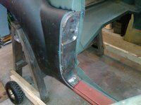
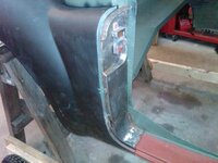
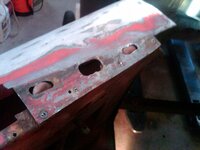
mission today is the drivers side shut face panel and the rear light plinth

IMG04943-20141221-1041_zps8662c7dd.jpg

sanded and primed

IMG04944-20141221-1105_zps0db84578.jpg

the problem
IMG04945-20141221-1108_zpsbb7d28e1.jpg

IMG04946-20141221-1108_zpse52c2e72.jpg

IMG04947-20141221-1122_zps6ba0454c.jpg


new piece test fit
IMG04948-20141221-1126_zps41d72dd2.jpg

IMG04949-20141221-1150_zps5061207c.jpg
IMG04950-20141221-1242_zps24e29b3e.jpg

IMG04952-20141221-1310_zps4d85a642.jpg

IMG04953-20141221-1310_zpsdde593e4.jpg
IMG04954-20141221-1327_zpsc42d6bcc.jpg

IMG04956-20141221-1400_zpsbd7c6ec3.jpg
IMG04957-20141221-1400_zps658f56c1.jpg
 
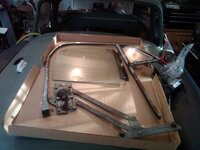
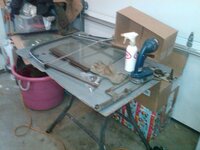
removed the door glass and frame from the drivers side.....no matter how much I read the instructions in the shop manual I could make no sense out them.....so I just did it my way....

some screws holding things down
IMG04978-20141227-1156_zpse791fc8b.jpg

IMG04986-20141227-1159_zps6e581934.jpg

the rivets hold the door skin to the metal frame, I drilled them out because I wasn't sure

IMG04979-20141227-1156_zps6d778bf4.jpg


the usual grinding was required to remove several bolts

IMG04998-20141227-1453_zpsb9872e2b.jpg

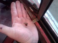
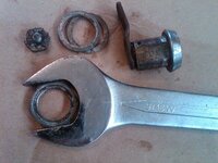
I found what a barrel nut was the hard way, there was a screw holding the front of the trim down and I couldn't figure out how to get at so after a couple hours of frustration I cut it

IMG04993-20141227-1434_zps0803c91b.jpg


IMG04994-20141227-1438_zps0df90f64.jpg

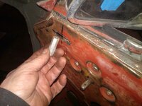
a barrel nut
IMG04996-20141227-1439_zps4674f75f.jpg

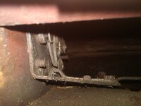
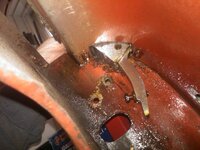
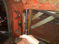
this is where the barrel nut attaches inside the door frame.....I have no idea how you are suppose to get to it though. I will see if I can figure a different way on the pass side now that I know how it all fits together

IMG05001-20141227-1504_zpsed4962b5.jpg

IMG05004-20141227-1505_zps32beb0a2.jpg


IMG04999-20141227-1502_zpsad46a65d.jpg
 
even after taking it apart on the one side I don't know how you do it on the other side..... some how you have to remove all the door locking components, then raise the window so you can remove it from the cranking mechanism, then remove the cranking mechanism so you can get at those barrel bolts then the window and the frame can be taken out???? I have not figured out how remove the window crank mechanism when the window is still with in the frame and the frame is still in the door .....I may be making an access hole some where to help this situation out. and did I mention that the window crank mechanism has like zero clearance to be pushed out and I could only do it after I had the window frame out...and as always "installation is reverse of removal"


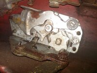
lets get all the door handle and locking mechanism components out

IMG05005-20141228-1045_zps7209236b.jpg

IMG04985-20141227-1158_zpsb3fd4dcb.jpg


use a tooth brush to clean the threads off no need to make the situation any harder then hit with PB blaster

IMG05006-20141228-1045_zps16367a2b.jpg

IMG05008-20141228-1045_zpsa5d2d5bd.jpg

and of course the lock retaining nut is 9/16W which is just a tad bigger then 1" the key code is stamped on the cylinder, the key cylinder retaining nut will slip off the back after the small bolt is removed and the cylinder will come out

IMG05009-20141228-1114_zps9aa8bbb7.jpg

and lastly letting the door handle machine screws soak for a little while

IMG05011-20141228-1118_zpse6d52332.jpg


these door mechanisms are a PITA most due to the cramped space
 
Last edited:
this is whats left of the window seal

IMG05018-20141228-1219_zpsb196576f.jpg

so now i move on to the pass side with my new found knowledge of whats holding it down....well after enough of sticking my hand every where I could think I found this position for the back barrel bolt

IMG05019-20141228-1240_zps581d3312.jpg

I tried every conceivable way to get at the front barrel bolt but an inner door support was in the way no matter how I moved my hands. strangely there was a 3/8" hole in the bottom of the door in the area of those two barrel bolts but I still couldn't get at the front one.

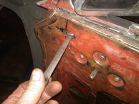
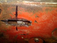
so I marked the location of the barrel bolt using the other side as the guide
IMG05023-20141228-1336_zps54f7ca23.jpg

so I made an access opening
IMG05024-20141228-1340_zps351f0db3.jpg

can you see the support bracket the barrel bolt is sitting on?
IMG05025-20141228-1341_zps2945d4c1.jpg
IMG05026-20141228-1342_zps103f1d60.jpg

and my access window
IMG05028-20141228-1344_zpsaae0f526.jpg

and it slipped off the bracket as I loosened it and moved down

IMG05029-20141228-1348_zps58b25e7f.jpg

IMG05030-20141228-1350_zps010d2912.jpg

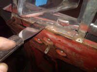
loosen up the caulking
IMG05031-20141228-1355_zps16af9b48.jpg

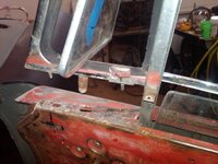
and I win, if you had any sort of a seal left you would need to remove the horizontal chrome finishing piece that covers it
IMG05032-20141228-1403_zpsfc3e9fa2.jpg

IMG05033-20141228-1420_zps5683f7e3.jpg
 
I bet they put the door skin on after they assembled the innards... as I said "where their cries for help will go unheard" or better, where no one cares.
 
I bet they put the door skin on after they assembled the innards... as I said "where their cries for help will go unheard" or better, where no one cares.

i can tell you that any one who has done this before falls in the where no one cares category...when i get a moment with everything out of the door i will put the frame back in and see if my hand can even reach up there, if not i make my access hole a little bigger and be done with it. there may be some strange combination of putting the parts in and tightening them up that makes this doable.....almost like putting headers on an engine in a C3......you fart around with it for 30 mins then it finds the right angle and slips in.
 
I bet they put the door skin on after they assembled the innards... as I said "where their cries for help will go unheard" or better, where no one cares.

i can tell you that any one who has done this before falls in the where no one cares category...when i get a moment with everything out of the door i will put the frame back in and see if my hand can even reach up there, if not i make my access hole a little bigger and be done with it. there may be some strange combination of putting the parts in and tightening them up that makes this doable.....almost like putting headers on an engine in a C3......you fart around with it for 30 mins then it finds the right angle and slips in.

C3 is easy - V8 conversions on S-10s. There's this magic moment when you realize that you have to pull the motor to get the right side header into the truck... bad words tend to happen just after that magic moment. :clobbered: Those words are especially poignant when you've already plumbed and wired the motor... want to guess how I know this?
 
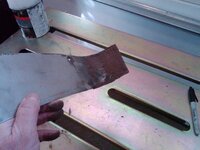
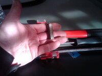
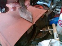
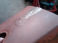
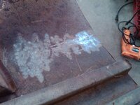
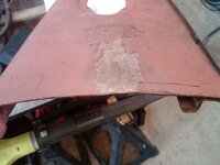
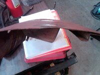
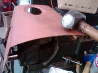
today I cleaned up the door windows and packaged them up for safe keeping. the question was posed to me would a planishng hammer work well to remove a crease. this was the go to tool back in the 30 and 40s to remove creases when the metal was good quality and pretty thick...so lets see how it does on an mga body panel

IMG05038-20150109-1135_zpsbe041ae3.jpg

IMG05039-20150109-1135_zpsc97f093a.jpg

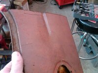
lets make a crease
IMG05040-20150109-1136_zps787f769a.jpg

IMG05041-20150109-1136_zpsaba9071f.jpg

IMG05042-20150109-1140_zpsa65b217a.jpg

about 1 minute on the planishing hammer

IMG05043-20150109-1144_zps5f295c28.jpg

IMG05044-20150109-1144_zps6d1063c0.jpg

heres the rub the distortion it introduces

IMG05045-20150109-1144_zpsbdbb602b.jpg

IMG05046-20150109-1145_zps8a66ac47.jpg
IMG05047-20150109-1145_zpsbedde35b.jpg

IMG05048-20150109-1146_zps7d009461.jpg

IMG05049-20150109-1146_zps6b3b8643.jpg


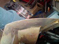
so with very little effort the crease is gone but some distortion is introduced.... I didn't take any time with this and did it very quickly you may be able to go slower and find the sweet spot to stop at or just add some heat to shrink the metal.
 
Back
Top