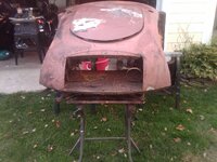
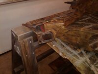
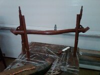
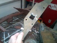
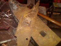
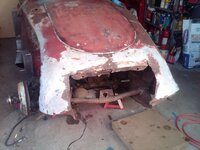
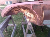
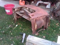
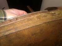
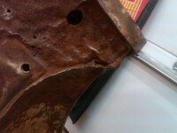
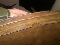
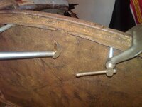
1958 MGA Coupe

VetteMod - Corvette Restoration, Modding & Performance Forum

Help Support VetteMod Forum:

well here is another bite of the elephant and may be the last thing i had to do before i can wrap up this side.

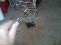
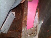
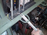
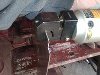
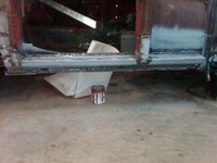
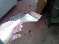
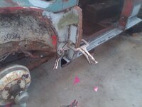
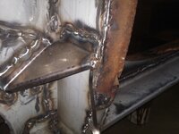
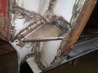
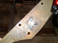
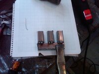
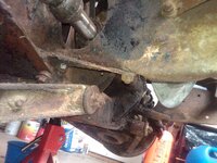
this is the foot well body mount and bolt
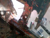
IMG00894-20121110-1354.jpg

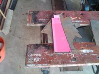
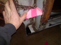
this is the template cut out of thin cardboard
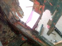
IMG00895-20121110-1411.jpg

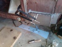
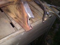
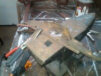
this is it laid out on a piece of austin healey 3000 frame i had laying around
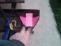
IMG00897-20121110-1412.jpg

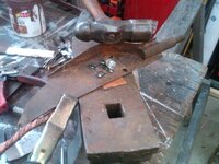
some slight persuasion happening

IMG00898-20121110-1423.jpg

IMG00899-20121110-1423.jpg

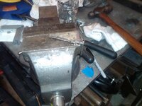
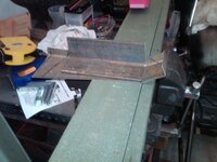
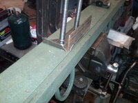
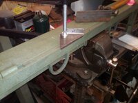
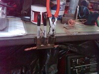
some times things dont fit in the vise to bend when the sides are already bent so i used a piece of flat stock to make the jaws wider
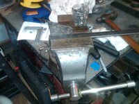
IMG00900-20121110-1424.jpg

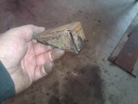
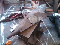
the rough shape

IMG00901-20121110-1444.jpg

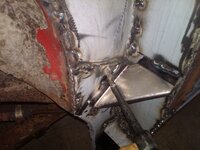
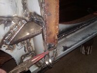
all seams are welded here is the final fitting and welding
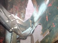
IMG00902-20121110-1514.jpg


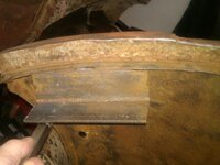
to make a nice rounded fit around the bolt hole i used an old steel washer welded to the bottom of the bracket
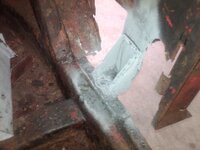
IMG00903-20121110-1530.jpg
 
thks guys

happy Veterans day to everyone thanks for your service, I actually think about all those who came before me and gave me the right to vote when I am in the voting line.


worked some more on the finishing the pass side.
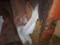
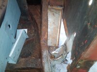
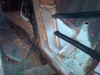
heres the need for the inner panel

IMG00906-20121111-1106.jpg

heres the template for the inner panel

IMG00908-20121111-1129.jpg

IMG00907-20121111-1127.jpg

here I am bending the piece

IMG00910-20121111-1150.jpg

IMG00912-20121111-1153.jpg

this is how you get extra leverage with brake

IMG00913-20121111-1156.jpg

IMG00914-20121111-1220.jpg

IMG00919-20121111-1320.jpg


now to fit the big panel and creat the flange< it its upside down in the photo

IMG00921-20121111-1351.jpg

IMG00922-20121111-1351.jpg

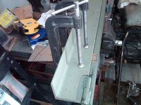
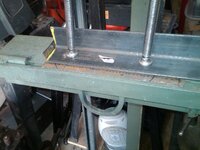
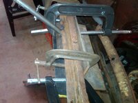
these are deep C clamps I use on the sheet metal break and are good for many things

IMG00923-20121111-1429.jpg

IMG00924-20121111-1430.jpg

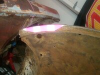
you can see the good penetration by the heat discolortation on the panel

IMG00925-20121111-1448.jpg
 
As an Amazon Associate we earn from qualifying purchases. Product prices and availability are accurate as of the date/time indicated and are subject to change.
My god, that car is a metal swiss cheese and you'll filling all the hole one by one.
This is crazy, in a good way :nuts:
 
yes lots of swiss cheese but whats good about this project is that there is very litttle out of pocket expense on this, just welding consumables. i needed a project this time that was more time intensive than $$$ intensive. I am still recouping from a wedding this past summer.

well we are getting close to wrapping up this side....

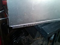
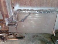
heres the panel fitted in place for welding

IMG00927-20121112-1242.jpg

I added the supports for under the door posts and painted the inside with cold galvanizing primer over the weld through primer and then 3 coats of rustoleum glossy black

IMG00928-20121112-1338.jpg

here the interior with gloss black. I will use the mig welder for the welding on this and I will grind away the paint that is exposed prior to welding

IMG00929-20121112-1339.jpg

heres the test fit before the third coats of paint and I will let dry before I weld it in place.

IMG00930-20121112-1357.jpg
 
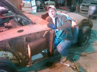
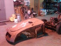
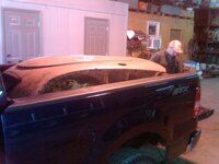
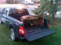
What a great day yesterday was! I got to go on a road trip with my oldest son, meet fellow NAMGAR member George Kress , work on an MGA and Tour George's car collection. George had been watching my post and realized he had exactly what I needed and offered a donation to the cause of a front shroud, front frame extension, and unbent radiator. I glady accepted this generous offer! Our road trip started at 6:00am yesterday and we reached George's shop by 9:30am. We started the dissassembly process and by 11:20 the three of us had wrangled the front end off the parts car. After we got the Shroud loaded into the Pick up the fun really started and we toured George's extensive car and parts collection and enjoyed every moment of it. About 12:30 we had everything loaded up and headed back home. It was a great Day with my son and it was really enjoyable meeting George and I look forward to seeing him again at one of the NAMGAR car shows....maybe even with my coupe wearing the new front end!

IMG00936-20121117-1041.jpg

IMG00940-20121117-1054.jpg

IMG00941-20121117-1059.jpg


IMG00939-20121117-1053.jpg

IMG00946-20121117-1126.jpg
IMG00949-20121117-1137.jpg

IMG00952-20121117-1655.jpg
 
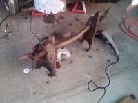
Front frame extension

well i got to work this am on removing the front frame extension from the shroud and worked on it a little bit to bring it back into tip top shape. one of the bumper mounts got bumped when the car got moved into the shop and it broke off when i removed the frame extension and it will get welded back on later this week


IMG00962-20121118-0847.jpg

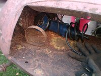
here is how i will remove the bolts

IMG00974-20121118-0932.jpg

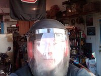
i take this stuff serious and i gear up for it and use a full face mask, hearing protection and thick leather gloves, not like these numb nuts on TV who use no protection

IMG00975-20121118-0933.jpg

IMG00978-20121118-1000.jpg

here it is removed

IMG00981-20121118-1034.jpg

all and all its in pretty good shape and way better then my mangled one on the coupe

IMG00983-20121118-1035.jpg

here are the side extensions hammered back to shape, it didnt take much

IMG00984-20121118-1112.jpg

working out a little dent, we wont let momma know i am using her potting table...

IMG00987-20121118-1128.jpg

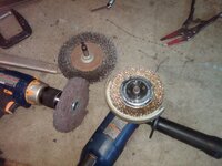
here it is wire brushed

IMG00990-20121118-1154.jpg

IMG00989-20121118-1154.jpg

I printed off of Barneys site the front frame extension dimensions and will use that as a guide to finishing the reworking of the piece
 
Nice work. I love how many people you meet in this hobby because of doing your build on the 'net. People you'd never meet had you not taken the time to photo document and build

I agree about the safety stuff, my favorite are the ones welding without gloves (ouch), or long sleeve shirts.
 
How do you..? Where do you..? What is that...? I don't even...

You my friend are a glutton for punishment! Are you sure there was really car there? The amount of sheet metal work is very impressive! Great project.
 
thks guys some more nibbles tonight....and time to wrap up this side.....tonight I welded the inner sill and patch panels into place. I spaced the welds about 1" - 1.5" apart and started at the middle and worked my way out, metal has a way of growing on you when it gets hot. tomorrow i will go back and fill in all the voids and grind the welds down

heres the trial fit

IMG00991-20121119-2028.jpg

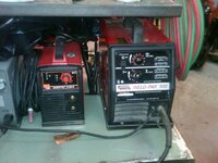
heres the welder for the sheet metal using .025 wire, I have welded more with this welder then you can possibly imagine and it keeps on going.

IMG00992-20121119-2037.jpg

heres the last of the welding, its important to have lots of clamps or vise grips holding things tight

IMG00993-20121119-2147.jpg
 
I finished the inner sill welding tonight I used a wire brush to make sure that there was no paint left bewteen the areas I was welding>

IMG00994-20121121-1552.jpg

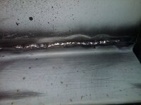
its important to inspect the welds....if you look closely you can see my bead in the middle is a little too high and moves off the bottom piece. look for the straight shiney line. ths is no big deal just lay another bead along side of it.

IMG00995-20121121-1552.jpg

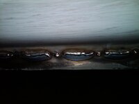
heres a good example of the original tack weld and then the follow up running bead

IMG00997-20121121-1602.jpg

now just have some grinding to do and we can paint it

IMG00999-20121121-1641.jpg
 
well while the turkey was cooking I snuck out side for an 1.5 hrs...
the need...


IMG01008-20121122-1017.jpg

clamp the metal to cut it with an electric shear


IMG01009-20121122-1035.jpg


IMG01011-20121122-1041.jpg

you can also use the break to hammer form the metal

IMG01012-20121122-1044.jpg


IMG01013-20121122-1051.jpg


IMG01014-20121122-1052.jpg


some times the clamps will not reach where you want them to go so just tack it and use a hammer to flatten out the seams

IMG01015-20121122-1104.jpg

ok this is just because i can...i am filling up a gap

IMG01016-20121122-1107.jpg

IMG01017-20121122-1108.jpg

IMG01018-20121122-1110.jpg
 
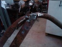
a few more nibbles of the elephant tonight, I used the O/A rig to put this back together and to bend it back into shape I still have a little more to do tomorrow to it.


IMG01025-20121123-1651.jpg

IMG01024-20121123-1651.jpg

IMG01022-20121123-1648.jpg

IMG01026-20121123-1711.jpg

IMG01027-20121123-1726.jpg

IMG01028-20121123-1727.jpg

IMG01031-20121123-1737.jpg
 
today everything fought me.....so I am calling it quits after a few hours, some times you have to know when to back off....


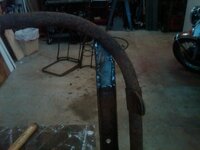
I did get the frame extensions bent back to the right dimensions though

reworked side

IMG01039-20121124-1128.jpg

original good side

IMG01036-20121124-1020.jpg

IMG
 
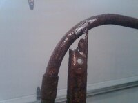
well I decided to try my luck again and it went much better, I fixed the hole in the tubing on the frame extension and then primed it.

IMG01040-20121124-1934.jpg

did a little bit of grinding and test fitted the other bumper bracket

IMG01041-20121124-1942.jpg

and then to the primer, i am so old i still think of it as red lead primer

IMG01043-20121124-1956.jpg
 
another hour or so this am after little Joe went back to college


cutting out the rust

IMG01044-20121125-1024.jpg

the filler piece from scraps

IMG01045-20121125-1038.jpg

the set up

IMG01046-20121125-1041.jpg

the tack

IMG01047-20121125-1042.jpg


the copper so it doesnt burn through and stick to my anvil

IMG01049-20121125-1043.jpg

voila

IMG01050-20121125-1058.jpg

this is the last time i am going to spend time looking for sharpies, my mig pliers or the ground strap

use graph paper to line it all up

IMG01051-20121125-1124.jpg

IMG01052-20121125-1142.jpg

painted

IMG01053-20121125-1211.jpg

IMG01055-20121125-1212.jpg
 
woohoo never put a grinder with a cut off wheel in the hands of a 55 year old....


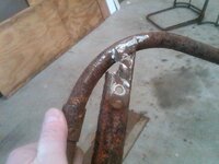
looks like the bottom of the frame horn is tweaked slightly

IMG01063-20121201-1120.jpg

I took many photos of hood gap for reference pictures

IMG01074-20121201-1200.jpg


removed old frame extension

IMG01075-20121201-1216.jpg


comapred it to the new one and they line up where they should and are different where i would expect them to be

made some imaginary cut lines way forward of where i think i am going to splice them
IMG01077-20121201-1302.jpg

and then made a different cut line even more ahead of those
IMG01079-20121201-1309.jpg

IMG01081-20121201-1313.jpg

spent a few more minutes fitting the frame extension i just had to hammer down one of the front frame horns a few mm's took about 3 hammer swings to get it right...time to contemplate the next move

IMG01089-20121201-1530.jpg
 
Last edited:
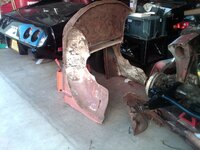
nibbled some more today on the elphant (about 2.5 hours)....i think i have decide to replace the entire wheel well and use the lap seam on the side of the inner wheel well. this will give me no unusual seams on the inner fender. the inner wheel wells that i have are from a later model year and have different stamped indentations, so i think i will just the entire inner fender at this point and use factory seams


IMG01093-20121202-1140.jpg

IMG01094-20121202-1141.jpg

IMG01097-20121202-1208.jpg

i fitted a ply wood radiator for ridigity and wire brushed the valance and inner wheel wells

IMG01099-20121202-1322.jpg
 
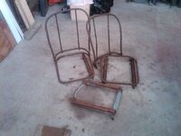
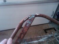
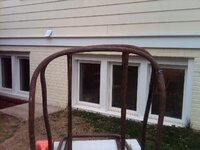
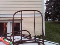
I needed to do some clean up in the garage and needed a quick hit on the car, so i grabbed the seats and did some work on them. i cut the old seat tracks off and welded a repair piece into the rail on one so we could wire brush it.

IMG01104-20121230-1238.jpg

IMG01106-20121230-1317.jpg

IMG01107-20121230-1318.jpg

IMG01108-20121230-1337.jpg

IMG01109-20121230-1338.jpg

IMG01110-20121230-1339.jpg

IMG01111-20121230-1353.jpg
 
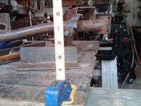
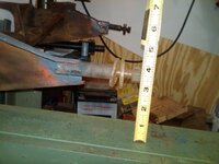
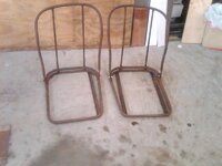
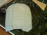
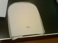
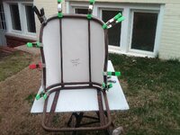
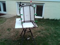
some more light work today.....i am making templates of the seats to figure how to make the roadster seats into coupe seats. really no surprises both the roadster seat frames and the coupe leather seat covers appear to me mirror images of each other. what i am missing is the height measurement of the coupe seat. i dont think i will have a problem cutting the frame tubes and making the seat backs to have the same curve but i really need the height measurement of the internal two vertical supports.


IMG01113-20130101-1233_zpse2466ab1.jpg

IMG01117-20130101-1246_zps3baa293f.jpg

IMG01118-20130101-1328_zps391eb7c9.jpg

IMG01122-20130101-1347_zpsb6a111a6.jpg
 
well no guts no glory....lets mock this thing up. from all of the templates it looks like if i make mirror images of both short sides i will be really close

IMG01123-20130101-1538_zps107d8ab6.jpg

IMG01124-20130101-1547_zpsc764e8dd.jpg

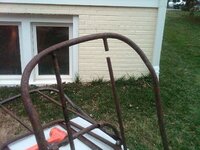
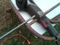
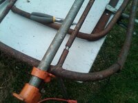
i cut a 1" piece of the solid stock to use as a locating pin
IMG01125-20130101-1550_zps6e59431c.jpg

i used a wood pipe clamp to pull the sides together
IMG01126-20130101-1603_zpsb0719ab4.jpg

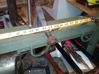
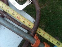
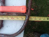
i decided to make the sides the same size and will use the outside measurement of the tape measure since there are no weld beads to interfere with the measurement
IMG01127-20130101-1603_zpsfa4549c9.jpg

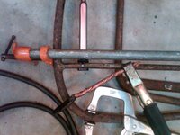
i used an axial clamp ( thks to Santa) to make sure the tube aligns properly
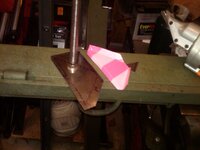
IMG01128-20130101-1610_zps2a51ef6f.jpg

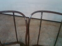
here you can see where i tacked the out side bend and this is with the two seat backs next to each other

IMG01129-20130101-1623_zps7d7f4084.jpg

and heres the final mock up all tack welded up.

IMG01130-20130101-1624_zps2a73aede.jpg
 
very much horse hair type stuff

i finished the coupe seat conversions and primed the drivers side inner sills and worked on the front shroud some


heres the finished seat back

IMG01137-20130105-1628.jpg

the primed sills

IMG01139-20130105-1629.jpg

IMG01140-20130105-1629.jpg

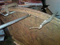
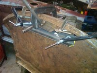
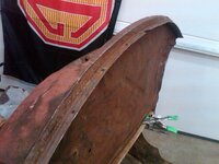
and now for the shroud work i am straightening it out a little bit at a time


heres the pattern

IMG01141-20130105-1630.jpg

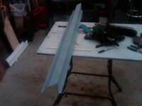
heres the tool a piece of angle iron with a handle welded on it

IMG01134-20130105-1628.jpg


heres a low spot that has been hammer formed by slipping it under the radiator duct valance and hammering it,

IMG01135-20130105-1628.jpg

IMG01136-20130105-1628.jpg


i worked on this for a little while and you can see it start to un wrinkle itself, the idea is to work it a little bit at a time in the reverse order the damage handled

IMG01138-20130105-1629.jpg
 
Last edited:
i was thinking about this and just needed to go back out and play some more, unfortunately earlier today i found out that my camera doesnt give me a warning when the memory is full and the photos stop getting saved. So a lot of the before pictures are gone but lets try and reconstruct

here if you look closely you can see where the bottom of the flange is pushed up towards the radiator duct valance

IMG01135-20130105-1628.jpg


so the idea is to figure out a way to apply the least amount of force to get it to come back to shape. sometimes you just have to play with setups to get the results you want. so there is a large 5x5 angle iron on the inside and then other angle iron on the out side so my lever only moves the piece of metal that i want to deflect. and my radiused hammer form is clamped so the lever is rocking against that so i dont distort the radiator duct valance

idea is to lever the piece down

IMG01144-20130105-2043.jpg

IMG01145-20130105-2043.jpg

IMG01146-20130105-2059.jpg

IMG01147-20130105-2100.jpg


and the final result

IMG01148-20130105-2104.jpg
 
your metal skills are top notch.

your decision to build that car rather than start with a clean sheet of metal - is pretty cool as well :thumbs:
 
Back
Top