1969 427 restoration from Sweden

VetteMod - Corvette Restoration, Modding & Performance Forum

Help Support VetteMod Forum:

Ok, frame measurements for JeffP1167:
Distance between inside of frame right behind the engine beams: 725mm which eaquals 28.5".
In front of the beams, if I measure exactly below the washers for the upper cross shafts: 675mm, 26,6".

Hope this will be of some help to you!
 
Hi all,

Been away for a while. Busy working on the Corvette... My internet connection has also been down for 2 weeks since the last storm. One good thing about that is I have not wasted time staring at the screen drooling at all nice Corvette builds:lol:

Anyway, had my carburator restored by a guy here in Sweden. He is a master on Rochester quadrajets and well known for his builds for dragrace cars as well as original cars.

Unfortunately my carburator was not the original unit. And, it was not even set up for my 427 engine. It also had alot of wrong parts and incorrectly assembled parts...

This is his findings, translated by me, so please have some mercy on my translation, alot of difficult words for a Swede involved here..

"Application number 7029207 says that it is supposed to be assembled to a 1969 Chevy 325Hp 350Cui V8. It was manufactured day 24 1975 and this makes it a Service Replacement unit for this engine.

During disassembly I noticed following:
The cover over the float housing ventilation incorrectly assembled.
Secondary throttle blades opening too much caused by a faulty linkage.
Dampening spring for the primary needles incorrectly assembled. This prevented the movement of the needles.
A pipe for the secondary acceleration pump was loose at the drivers side.
A clip for the intake valve incorrectly assembled causing a risk for fuel leakage.
Throttle bushings worn.
Main jetting too lean for a big block.

All faults above corrected.
New bushings for throttle shafts assembled.
Main Jetting changed.
Acceleration pump rubber changed to ethanol resistent material.
Recalibrated the Idle circuit for your big block specification."


The Carburator looks almost like new and I´m very pleased to have a Rochester 4MV on my 427 engine.
Here it is on my original aluminum intake, glass blasted.

18774f0b5cf7780d8.jpg

18774f0b5cf8ca4f4.jpg
 
Last edited:
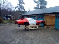
Have put some work on my ( well, the Corvette´s) body now.
Started by washing it all with a high pressure washer. Then allowed it to dry in my workshop for a week or so with a heating fan blowing hot air over it.

18774f0b5cfa27b6a.jpg
 
Last edited:
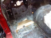
Then it was time to remove all paint and other nasty stuff on the inside of the body. A lot of cracks and holes all over the floors was present. The connections in the floor for the drivers side seat was all completely cracked! What a suprise to fall through the floor while driving:crutches:

Photo shows the large hole at the drivers side. I wonder what has happened here?

18774f0b5cfb6dc36.jpg
 
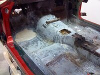
Everything grinded with 80 grit sand paper and thoroughly washed with Acetone. As may be seen, the first layers of woven glass fibre mat has been fixed in forward section and also at the seat connections.
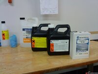
Im using a very flexible woven mat that forms around every corner and bend without making bubbles or sharp edges. I use Epoxy resin for all of this work.

18774f0b69d84de60.jpg

18774f0b5cfcb6ff5.jpg
 
Last edited:
As an Amazon Associate we earn from qualifying purchases. Product prices and availability are accurate as of the date/time indicated and are subject to change.
Check where the transmission tunnel joins the firewall. There is a sharp transition there and the join will usually crack. It does not open a gap so you can't see it. Mine discovered mine was cracked when I was scraping glue with a knife and went right through.
 
Check where the transmission tunnel joins the firewall. There is a sharp transition there and the join will usually crack. It does not open a gap so you can't see it. Mine discovered mine was cracked when I was scraping glue with a knife and went right through.

Fortunately that connection was ok. I have thoroughly looked on all joints and I have found a few separated. Especially at the lower parts of the fenders where they connect to the wheel housings. Have glued it all back together with the Epoxy. Mixed a speciall substance in to the Epoxy that makes it thicker so that it stays in place!

Anyway, thanks for the tip BBShark!
 
I precut all mats before mixing Epoxy. No time to do this when the epoxy is mixed... Only mixed a small quantity of Epoxy at a time.

Put down 2 layers of glass fibre weave, doing one side at a time. Finished with 1 layer of carbon fibre weave. Just to give it all some extra strength:D

Of course all hardened Epoxy was washed with a citrus (!) mixture to remove remains of resin that forms on epoxy during the hardening process. (this was recommended by the epoxy manufacturer).
Sanded all surfaces where new weave meets old weave as well, before starting on the other side.
Has not finished the tunnel and passenger side on the last photo.

I will willingly admit that this work is not particularly beautiful... but, it really seems to give the inside of the car a more stable feeling, almost like sheet metal!

18774f0b5cfc190ac.jpg

18774f0b5d92ea9d5.jpg

18774f0b5cfd6a93b.jpg
 
Last edited:
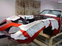
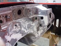
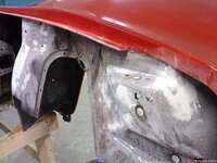
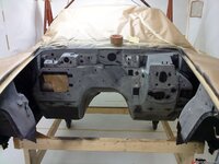
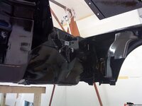
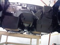
Finally got started on the paint prep work. I will paint the complete under side and engine compartment.
Grueling work, laying on the garage floor sanding the bottom of the chassie...

A few photos of the engine compartment.
18774f253afb2fd7f.jpg

18774f253afbd8867.jpg

18774f253afc838b7.jpg
 
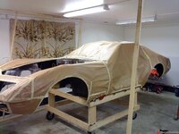
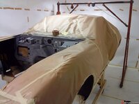
After getting the outside of the body completely sealed I built a very non professional paint box:D
I have done this before and it actually works rather good. A few 1"x2" planks screwed between the roof and shop floor. Then everything is dressed with paper from the inside. I live near a large paper plant producing very smooth, high quality paper for cigarette packages and food boxes giving me access to the product.
The end result is a dust free and protected enviroment for the paint job.
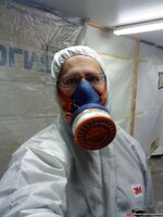
I normally cut a few openings around the box and plug them with a filter material where fresh air can flow in. At the opposite end I connect my weld fume fan, it has a very high capacity.

18774f253af9eb22f.jpg
 
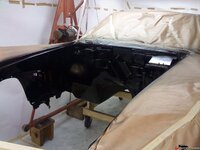
Top paint sprayed. 2k semi gloss. The photo was taken when the paint was still wet so it is not as shiny as it looks... However I think it still is a little bit too shiny but I just cant make my self start all over again sanding down the complete underside of the body.
18774f253af8b1d6e.jpg
 
What's up with the first few photos? When I click on them I receive the following message:

JE Caudle, you do not have permission to access this page. This could be due to one of several reasons:
  1. Your user account may not have sufficient privileges to access this page. Are you trying to edit someone else's post, access administrative features or some other privileged system?
  2. If you are trying to post, the administrator may have disabled your account, or it may be awaiting activation.
 
Last edited:
Hi,

I actually have no clue to your problem. I can see that the pictures are very small but when I click on them they are enlarged on a new page.

I am back working on my car after a long stop due to having a lot to do at my job...

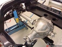
The rear end is now complete and the chassie is back on the wheels.
I´m waiting for my newly machined engine block to get back and then I will start the assembly of my engine.

I willl update with pictures soon.

Regards, Daniel
 
What's up with the first few photos? When I click on them I receive the following message:

JE Caudle, you do not have permission to access this page. This could be due to one of several reasons:
  1. Your user account may not have sufficient privileges to access this page. Are you trying to edit someone else's post, access administrative features or some other privileged system?
  2. If you are trying to post, the administrator may have disabled your account, or it may be awaiting activation.

The photos open in a new window, I'm guessing that it's a browser issue...
 
I get the same message, on the 2nd and 3rd post..not the 1st. I'll have to see what's up. Can you open them Karsten? I'm wondering if the actual photo is gone somehow...
 
Just checked, the ones we can't access are set to private. If you change them to public we can see them again.

This is only a prob is you use the thumbnail link or the quick gallery option.If you post the auto resized full size (with the yellow toolbar) it won't matter because you shared the link to the private pic
 
I hope the photos in the first posts can be viewed now!
I set them to public.

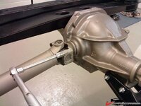
So, I finally recieved my completely restored differential. It is restored by a very skilled man here in Sweden that has been building rear ends for dragracing and street use for decades...
He buys a lot of his stuff from Tom´s and well known US manufacturers.
It has a new Eaton posi unit, polished and with all the good stuff inside it. It will be more than good enough´for 500+ hp.

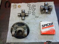
Assembly of the new 1350 Spicers. Made a plate to avoid warping of the parts during assembly. Had to grind a small radius in the ears to get the 1350´s to fit. I know Gary Ramadei also does this on his builds.

18774f99a8cb9f5a4.jpg
 
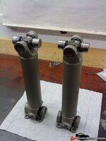
Right side finished. It all went smooth.

18774f99a8cc5c727.jpg

The only problem was the new strut rod bracket that is bolted to the diff.
The bracket was included in the Street and Slalom kit I bought from a well know company. I suppose it is the same bracket included in kits supplied by most of the companies. Anyway, as I was bolting it to the diff I discovered that the bolt holes in the bracket were so large that the bracket could be moved several mm from left to right:shocking:
Took out my old original bracket and test assembled it and it was completely tight.
So, another useless piece of crap that must be modified...
Machined small inserts for the too large holes and pressed them in to the holes in the bracket. This gave a completely tight fit.
 
Last edited:
The only problem was the new strut rod bracket that is bolted to the diff.
The bracket was included in the Street and Slalom kit I bought from a well know company. I suppose it is the same bracket included in kits supplied by most of the companies. Anyway, as I was bolting it to the diff I discovered that the bolt holes in the bracket were so large that the bracket could be moved several mm from left to right:shocking:
Took out my old original bracket and test assembled it and it was completely tight.
So, another useless piece of crap that must be modified...
Machined small inserts for the too large holes and pressed them in to the holes in the bracket. This gave a completely tight fit.

I've heard this before about the Smart Strut bracket.
 
Back
Top