need help with 6 link suspension setup

VetteMod - Corvette Restoration, Modding & Performance Forum

Help Support VetteMod Forum:

Joined
May 4, 2008
Messages
13
Reaction score
0
Hi everyone
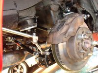
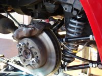
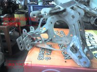
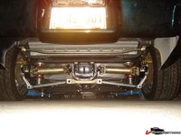
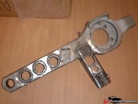
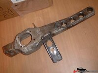
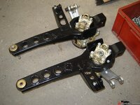
Here's my problem, I am rebuilding my rear suspension right now and need to get new trailing arms because mine are rusting from the inside. I recently came upon a set of trailing arms that are setup to be exactly like the 6 link setup that is in the sticky.
The problem is that that setup requires a shortening of the inner yokes, I really want to run this 6 link setup, but I don't want to be digging into my differential and taking out the yokes.
Is there any simple way to solve the problem of the binding in the yoke that can be caused by adding a second strut rod to the rear suspension.
Would it just be easier to pull the yokes and just shorten them?
Thanks in advance for any advice.
 
You should not have to shorten the yokes, instead you have to remove the clip that prevents the yoke from moving outward and thus allow the yoke to move freely in and out of the differential.
If you don't remove the clip it will shear off and then it's getting shredded by the gears.... if you have not opened the diffy you might as well inspect it now before you start reassembling. A HD cover is a good idea too: more "meat" where the spring bolts holes are, these often break on stock covers.
 
Call Dragvette and get a copy of the instructions. You can set the 6 link up with the c-clips installed.
 
As an Amazon Associate we earn from qualifying purchases. Product prices and availability are accurate as of the date/time indicated and are subject to change.
Do I need to completely disassemble the diff to get those clips out?
How much do those slip shafts go for?

No, you only have to remove the cover. This is the best time to replace the yoke seals and also inspect the rest of the diffy, at least have a look inside and see if you still have the C-clips... the yokes might already be worn down to the clips, who knows....
 
I'd like to see more about that suspension.
Any pics about the builup Stroker?

Yes......

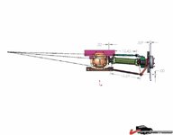
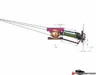
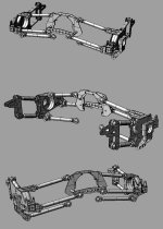
This is the 3D model (rhino) I used to study the configuration:
Immagine-tot.JPG

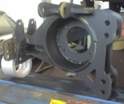
This is the first release in 6-8mm mild steel..... big and heavy!
WheelHub1.jpg

This is the hub in it's final configuration.... 3mm Stainless.... up to 3 layers spot welded where the bearing housing bolts
CUSHION.jpg

By the way I reversed the bolts.... with the head inside (under the park brake shoes) in order to be able to disassemble the unit withouth pulling the bearings!
 
The only other way is to get custom slip half shafts made vs. fixed length. Mine adjust from 13~15" in/out and cost about $500 for the pair.

6link064.jpg


6link062.jpg
 
Yes Stroker this is really cool. cant get enough of those modifications buildup
is the front suspension also modified?

Lucfr
I know a compay who does driveshafts for big trucks, I'll check if they can make some of those.
 
I talked to Twin_Turbo and he said if the strut rods are setup right, they can pull the yoke out so that it wouldn't have to be shortened, any ideas about going this method?
I will try to reach dragvette, but their setup is quite different from mine so I don't know if the same will apply.
 
I said, if the rods are set up to share the instantaneous center already set by the lower strut rod and halfshaft that the stub axle won't move. However after adjusting camber it won't be totally perfect anymore and you will have a little movement. For that you can remove the c clip and adjust both rods a little longer to pull the stub out a little to give it freedom of movement. The slip shafts are a much better solution because adjusting the rods out will increase the toe and you have to set that again (big PITA)

Lucfr, didn't know you had them also. They look great. Especially the fact that the splies don't show and they are sealed, no dirt can get inside. Where did you get those?
 
Here's the deal on the 6 link. I suggest you read this first: Tech Aticle: Roll Axis, Roll Center and Instantaneous Center

Now for a little more info. I used FlexusMark's pics.


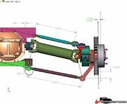
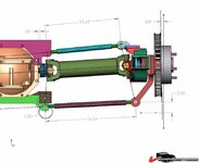
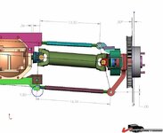
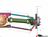
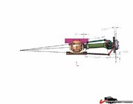
The following 3 pics are how you HAVE to do it if you want to stick with the stock fixed shafts and c clip in place. It's still recommended to remove the clip because you will only have the available play in your stub axle for tolerance and adjustability when adjusting the upper and lower strut rod. If you have to make significant camber adjustments this will lead to having to adjust each one a little at a time, alternating between the 2 to keep them from binding. It also means that you can't adjust the camber way off because of geometry constraints. It's therefore not recommended to keep the C clip. Without the c clip you can adjust the 2 rods to pull the stub out just a little. Sticking to this shared instantaneous center method will result in the least possible stuck axle movement. Because of tolerances and adjustments there will be some movement, ideally when strictly adhering to this setup there should be none but that's only in the ideal situation. Finding actual IC is problematic. It can be done roughly by stringing, then fabricating the mount and tacking in place (with no shock or spring load) and carefully adjusting for bind and stub axle movement.

Shared instantaneous center between lower rod, halfshaft and upper rod, shared pivot planes.
2481ee91e90868.jpg

2481ee91f33c2b.jpg

2481ee91fb5281.jpg

With this setup the camber curve will remain what is dictated by the lower strut and halfshaft. Even if the halfshaft is no longer a controlling member with the floating stub axle, it does determine the IC and therefore the geometry (and camber curve) When repositioning the lower strut (inner mounting point), this also translates into a new position for the upper one.

NOTE that apart from the instantaneous center, the 3 inner picots (and the 3 outer ones also) are IN THE SAME PLANE! Note the line though the rod ends and u joints. This is a requirement to get a perfect trapezoid.

In the 3 pics you can see that stub axle movement is at a minimum, with a .32" distance between stub and case.


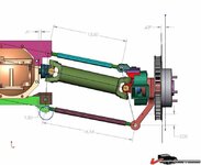
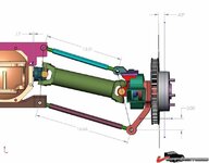
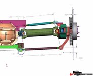
Next we have a setup where the camber bracket has lowered pivot points. This results in a parallel lower strut rod and halfshaft. A situation commonly used with "smart struts". This will result in a reduced camber curve.
An upper rod was also installed and the pivot point planes are shared amongst the 3 members. The 3 members do NOT share an instantaneous center and stub axle travel is increased. However, the camber curve is no longer the same as that set by the lower rod and halfshaft. This way you can create a curve that may suit your requirement. However the halfshaft and stub play are still limiting your setup, this is where the telescopic shaft comes in, they greatly enhance your possibilities. Not only for this setup below but for all the following ones and this will make it clear why it's easier to fabricate a 6 link that way because you won't have to strictly adhere to the IC & geometry set by the fixed halfshaft.

Shared pivot planes, non shared IC, parallel lower rod & halfshaft
2481ee921e8861.jpg

2481ee9227d02b.jpg

2481ee92362280.jpg

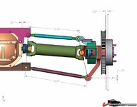
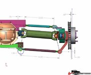
The same idea but the inner pivots are not in the same plane:
NON shared pivot planes, non shared IC, parallel lower rod & halfshaft
2481ee95c4025e.jpg

2481ee95d00ad2.jpg

2481ee95da443e.jpg

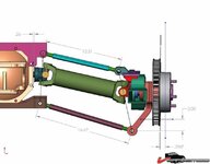
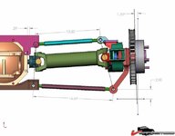
Yet another setup this time the upper rod is parallel to the halfshaft

Non shared pivot planes, non shared IC, parallel upper rod & halfshaft
2481ee95e9d0bc.jpg

2481ee95fdbfc2.jpg

2481ee960b55b5.jpg

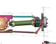
And nothing parallel.
Non shared pivot planes, non shared IC, no parallel rods & halfshaft
2481ee92047496.jpg

2481ee920d2757.jpg

2481ee9216be99.jpg

The situation where the outer pivots are not shared is not being discussed but it too will contribute to travel play and the resulting camber curve. The outer pivots are easy to plot with a completely assembled trailing arm assembly on the bench. The HEIGHT of the outer pivot is to be chosen wisely. The location means that it's right where your bumpstop is, so don't make it too high. Too low and you have to mount the inner pivot even lower, possibly too low to clear the spinning stub axle. A good idea is to mount it high enough to not interfere with the frame and/or the bump stop. Especially if you use a cut down bumpstop. Only after the outer upper position is determined can you select the inner one.

Most systems I've seen being fabricated have not been using the 1st method of shared IC & pivot planes. Instead a stud has been welded to the crossmember and a rod end attached. The resulting stub axle movement will be whatever it comes out to be although it can be reduced by reducing suspension travel.

I would rather keep my stub axle fixed, side movement must certainly contribute to wear, possible oil wicking out and wear of the seals. The splines will most likely wear out faster too. IMO the sliding shafts are the best way to go about fabricating/building your 6 link setup.

Stock setup
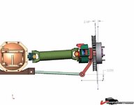
2481ee9615d76e.jpg

Smart strut type setup with lower inner pivot & reduced camber curve
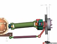
2481ee9620803e.jpg

A little bit about the smart struts. On other forums it's commonly said that parallel lower strut rods and halfshafts give you 0 camber gain! This is obviously false. It WOULD be true if the members would form a parallelogram, however they do not, they form a trapezoid and because of the angled sides they will give you camber gain because the effective perpendicular component changes between the 2 as the other 2 members (halfshaft and strut rod) angle away from horizontal. It's analogous to how a steering box steering system works, the center link is connected with the pitman and idler arm. These 2 are angled towards the rear diff, forming a trapezoid and thus alowing for different steering angles on the in and outboard wheel. This is known as ackerman.

 
Stock it's a good bit below horizontal.

There's a problem with a horizontal halfshaft. It resutls in toe oversteer because of the fixed trailing arm front bushing. If the halfshaft movess away from horizontal (either direction) the toe goes towards positive. Now, if you have your halfshaft set to neg. toe and it's below horizontal the toe will go towards more negative until it's horizontal and then back towards positive again.

V-Twins car is about "ideal" when it comes to how much it's lowered. With the tank full and driver & passenger on board the halfshafts are just below horizontal. The suspension is really stiff, it won't go past horizontal a lot.

You also don't want them perfecty horizontal most of the time, it promotes u joint wear. You want some angle in there.

Here's V-Twins IRS:
5480f33bfdcfdc.jpg
This means that if you lower the suspension to where the halfshaft is horizontal or even past this, all suspension compression will move the toe towards or even into the positive figures. To remedy this, you have to set a good bit of initial toe in to keep it from going towards toe out.

Anotehr way to do it is to raise the differential so that the car is lwoered but the halfshaft is just below level. This so it operates right around horizontal or below it. This way you won't have to set insane neg. toe or have rear oversteering (well, not as much, it still is a problem)
 
Cool, got that.
question, I didnt notice in other pics and cant find them right now. Is the trail VTwin arms has johnny joints at trail arms ends? And were they stock trail arms or offset ones.
 
Last edited:
No, stock rubber. When I was fabricating those arms i didn't have the johnny joints handy. Didn't feel like waiting and dropped the arms off @ the powdercoater so sadly for him, no johnny joints :)

They were bone stock arms:

2482071a48a65a.jpg

2482071a5a2cd9.jpg

2482071a70b714.jpg

The holes with the tubes welded in are supposed to torsionally stiffen the arms because of the way the shock loads the arm with the mounting arm. It tries to twist the arm and I didn't feel the skip welded (and porously welded) stock arms would be strong enough.
 
Ok thanks,
the holes maybe not necessary but they look cool for sure.
I'll have probably tons of other questions as I go along LOL

Hey about the tubing welded like that to torsionally stiffen the trail arms, do you think using that method to stiffen the frame help?
 
Last edited:
Wow, thanks for clarifying everything Twin_Turbo
I'll study all the setups you've posted and the link you posted as well, this should help me a lot in figuring out what exactly I'm doing instead of just jumping in blind. Great info:thumbs:
 
Last edited:
Ok after studying the pictures I've come to these conclusions
to run the stock stub axle with c clips still in the geometry needs to be setup just right and everything needs to have the same IC

If it is setup any different then the stub axle begins to move in and out.

What I'm wondering is what is the movement on the stock stub axle with the stock suspension? (basically how much movement is built into the stock suspension) Or is there no movement at all? And how much movement can be ok? I understand that any movement at all is bad because it increases wear on the yoke and seals, but is there a somewhat acceptable amount?

One other quick question, sorry if it's stupid I've never dealt with diagrams like this before, why does the length of the strut rods in the picture change as the same suspension is put in different positions?
 
Last edited:
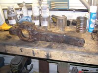
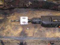
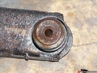
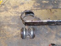
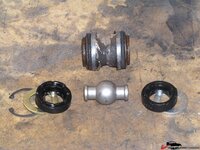
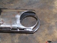
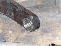
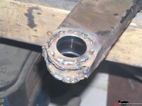
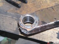
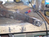
Here's a tidbit on the johnny joint install. All you need is the joint a hole saw, an undercut 7/16 drill (so the stock sleeve acts as a guide) and a welder. This isn't my welding, a buddy did this after I recommended the JJ to him.

You start off with a std. arm:
2482367bd418d7.jpg

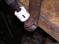
Then you have your hole saw w/ 7/16 drill with the shank cut down to fit the arbor, and use the stock sleeve as a guide:

2482367be43fc3.jpg

2482367bf8d3ab.jpg

Making the cut and removing the stock bushing:
2482367c0d19cb.jpg

2482367c32019e.jpg

Disassembling the 2" JJ. The outer sleeve needs to be welded into the arm:
2482367c4d1986.jpg

Cleaning up the bore and the surrounding metal for a clean weld:
2482367c764ac6.jpg

2482367c61ced6.jpg

Welding in the sleeve. The better you are at welding, the better the job will be done of course. However, penetration is the most important. Anyone can grind welds to make it look cleaner.
248236868e791a.jpg

2482368675033b.jpg

Finally a little grinding, some painting and final assembly and presto, one JJ equipped trailing arm for long smooth operation.
24823686a5d9e3.jpg

2482367bb21ce5.jpg

2482367bc3a38e.jpg

24823686c46f67.jpg
 
What I'm wondering is what is the movement on the stock stub axle with the stock suspension? (basically how much movement is built into the stock suspension) Or is there no movement at all? And how much movement can be ok? I understand that any movement at all is bad because it increases wear on the yoke and seals, but is there a somewhat acceptable amount?

Just the factory tolerance, or better the tolerance that's there now. In the ideal situation it should be almost zero. A .0005 enplay is tight, about .001 is the max I'd want it to be however it can be quite a bit more, up to over .05

That movement is especially bad because it messed up the camber setting, it makes the suspension "loose"

One other quick question, sorry if it's stupid I've never dealt with diagrams like this before, why does the length of the strut rods in the picture change as the same suspension is put in different positions?

FlexusMark did those pics, the dimensions should nto change, in some pics the lower struts are fixed dimensions, in some the upper. I don't know why he did that, it could be an oversight, it could also be a rounding error in the software depending on the settings. Considering the lengths should be absolutely fixed, you can assume that (especially for the example with nothing parallel, is aw some discrepancies there) that the stub axle play is actually more because of that tiny error.
 
What I'm wondering then is how did that 6 link kit thats posted in the sticky section work then? They say that they simply shave a little off the yoke so it can move in a little more and take out the c-clips so it can move freely in and out, do they basically live with the fact that there's going to be more movement due to the 6 link design and build it anyways? It does not look like they found the IC of all the components and used it to eliminate yoke travel, they just set the rods parallel to everything, that should make for a ton of movement based on the sketches here.
 
Exactly that! Shortening the stub does allow a little more movement (the max is when the dist shield hits the case, something that yous ee on diffs with heavily worn stubs sometimes)

Hey, it's corvette aftermarket stuff, if it bolts together and looks cool it must be the beez knees....if it works properly, or if it could be better? Who cares! There are tons of "products" that are available that fall in this category.
 
haha interesting
Here's the thing though, they supposedly ran .97 G's with that 6 link and a few other basic mods, many of which I have, so I'm thinking maybe its better to bite the bullet and see how long the yokes last with that setup and enjoy the performance gains, or is that all bs as well and I wouldn't actually see that big of an improvement

Also, if I go with slip shafts, is it a bolt on kind of deal? Do I have to custom fabricate anything? Do they completely solve that problem (as in no matter what 6 link setup I run I won't have to worry about the yoke as a source of problem in the geometry?)

This thread so far has been a great help, lots of info I would have otherwise never gotten:drink:
 
There's no actual performance gain. What it does is alleviate the stress on the halfhsaft/stub axle by taking it out of the susp. equation.

If you have a 6 link and a regular setup, both with the same camber characteristics and static settings, and the std. setup is tight with no excessive stub axle play, then they will perform the same.
 
I think it's simply awesome :) I have discussed it with him when he was in final stages of development. We discussed shock placement and such. It's much like the old greenwood setup (and the C4 one).

He should start selling DIY fab kits :)
 
Back
Top