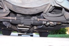
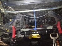
Rack and pinion - homemade Steeroids with GrandAm rack

VetteMod - Corvette Restoration, Modding & Performance Forum

Help Support VetteMod Forum:

Here's the plan for this week: I'll drill out the holes in the frame, the three holes that the long 4" bolts go thru, the three bolts that hold the main part of the bracket. The rearmost hole already has a tube inside the frame, I hope that hole is big enough for a 7/16" bolt, currently I'm using 3/8" Coarse thread, this is just during fitting this stuff, the final product will be held in place by three 7/16-20 fine thread bolts and lock nuts.... Plus four 3/8" coarse thread bolts on the underside of the frame.... Probably overkill but this stuff is what I'm going to use to steer the car, I consider it somewhat important.... :bounce::bump:

So the two foremost holes will be drilled and a steel tube welded to the frame - i don't want to take a chance and crush that frame when tightening the bolts :lol:
 
Looks good, speedway motors had good prices on all accessories. I used their threaded tie rods on my second hand steeroids set up.

You'll like the results.
 
Looking forward to get it down off the jackstands :D

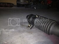
Ok, today's progress: drilled the passenger side rubber bushing to 51mm (2"=50.80mm) to fit the larger diameter of the manual rack... My 2" hole saw worked quiet well :D

photo_zps8ec3dfac.jpg

.

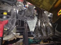
Started on the passenger side bracket and I can really now see it come together.... This is going to be awesome.....

photo_zps664a3f5b.jpg

.
 
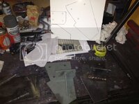
Since I had nothing better to do I started working on the templates and a second driver side bracket.... This one is 3/16" and it feels pretty solid once bolted in place.... I wonder what these vendors use to make their brackets... Sheetmetal ??? I think Marck commented at one time that the powdercoat seemed to be thicker than the steel that crap was made of..... :lol:

photo_zpsdf270f58.jpg

.

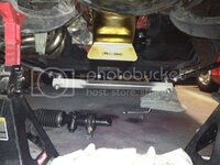
The 1" square tubing I'm using for the rack attachments and this center link is not the cheap shet from the hardware store.... It's actually .083" wall thickness so it's rocksolid....
.

photo_zpse0833999.jpg
 
You are going to raise the center link/bar much higher, than the rack traveler bolts, I assume......needs be about 4" higher at the inner tie rod ends....I made that error, and had the tie rods at the same elevation as the rack, and had a hell of a bump stear problem, one of the guys said to raise the tabs the tie rods went to....so they mount stud down/bolt on the bottom, keeping that pivot point high and that cut the bump steer to almost nothing.....


:gurney::drink:
 
You are going to raise the center link/bar much higher, than the rack traveler bolts, I assume......needs be about 4" higher at the inner tie rod ends....I made that error, and had the tie rods at the same elevation as the rack, and had a hell of a bump stear problem, one of the guys said to raise the tabs the tie rods went to....so they mount stud down/bolt on the bottom, keeping that pivot point high and that cut the bump steer to almost nothing.....


:gurney::drink:


Yup... here's one photo I found online, this is about what I'm going to do... not sure yet if I want to have the bolts vertical or horizontal.... bolts vertical allow for bump steer adjustment but limit the rod end movement a little....


rpcenter_zpsa2c0dd21.jpg
 
As an Amazon Associate we earn from qualifying purchases. Product prices and availability are accurate as of the date/time indicated and are subject to change.
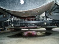
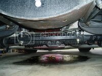
Something's dripping down there :D

Is the center bracket mounting pattern the same as on the power rack? Looks like it. I have a spare one from Speed Direct. Could come in handy sometime in the future if I convert to a manual rack setup.
 
You are going to raise the center link/bar much higher, than the rack traveler bolts, I assume......needs be about 4" higher at the inner tie rod ends....I made that error, and had the tie rods at the same elevation as the rack, and had a hell of a bump stear problem, one of the guys said to raise the tabs the tie rods went to....so they mount stud down/bolt on the bottom, keeping that pivot point high and that cut the bump steer to almost nothing.....


:gurney::drink:


Yup... here's one photo I found online, this is about what I'm going to do... not sure yet if I want to have the bolts vertical or horizontal.... bolts vertical allow for bump steer adjustment but limit the rod end movement a little....


rpcenter_zpsa2c0dd21.jpg

Due to the rack not being perfectly centered, and I forget just exactly why....maybe the steering input, maybe tire rubbing?? at any rate I have unequal tie rod lengths....19 and 21 inches as I recall.....

NOW, looking at your solution there, first off, I see Heim joints....I come back to that all the OEM makers use similar ball joint tie rod ends, and SO I don't trust heim joints....

then the other thought, as the wheels run up/down in a lean/turn, the push on the tie rods is rather multiplied with a long rod/strut in the picture above, and so will put too much force on the traveler/output block, twisting it in the rack slide, and forcing wear.....or failure....MY install was to just use longer tie rods, and surely maybe the handling was compromised, but methinks it takes a balls out racer to notice it....I think that long rod off the rack is a failure in the waiting....

:tth::flash::goodnight:
 
Something's dripping down there :D

Is the center bracket mounting pattern the same as on the power rack? Looks like it. I have a spare one from Speed Direct. Could come in handy sometime in the future if I convert to a manual rack setup.

NO - the power rack is longer than the manual rack and easier to mount. I just finished the passenger side bracket and my rubber clamp mount (stock Pontiac GrandAm or GM Cavalier) is located 4" off the frame towards the center.
The power rack mounting point could be 3" closer to the passenger side frame rail....
The driver side is identical.

Let me know if you want a set of brackets :D
 
Due to the rack not being perfectly centered, and I forget just exactly why....maybe the steering input, maybe tire rubbing?? at any rate I have unequal tie rod lengths....19 and 21 inches as I recall.....

NOW, looking at your solution there, first off, I see Heim joints....I come back to that all the OEM makers use similar ball joint tie rod ends, and SO I don't trust heim joints....

then the other thought, as the wheels run up/down in a lean/turn, the push on the tie rods is rather multiplied with a long rod/strut in the picture above, and so will put too much force on the traveler/output block, twisting it in the rack slide, and forcing wear.....or failure....MY install was to just use longer tie rods, and surely maybe the handling was compromised, but methinks it takes a balls out racer to notice it....I think that long rod off the rack is a failure in the waiting....

:tth::flash::goodnight:

The rack is not centered, you're correct. This is because of the unequal length of the rack...if that makes sense....here's what I did tonight: I turned the rack input shaft all the way from left to right, 3.8 turns..... Turned it 1.9 turns back and centered it..... Then I centered the inner tie rod bolts under the frame.... The driver side clamp is in line with my driver side bracket which is 1/4" thick.... Worked out perfect so far.

Now I have to rotate the rack so the the input shaft matches and is in line with the steering shaft.

Many have cut the engine mount horn - I don't see why.... The frame horn does not interfere with the rack input shaft, at least not in a way that cutting the frame horn would improve the steering shaft alignment....

Gene, post a photo at roughly the same angle as the one I posted.....
 
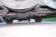
Here you go Karsten,


I have a power rack Grand Am, new from junkyard, your rack being manual and shorter? makes it hard for me to comment on how it's rotated, all I can say is that the input coupling was hitting the frame, so I cut a crescent out of it with a hole saw....I have only TWO universals one at the column, one at the rack, and a DD shaft in between, it happens to have a rubber isolator in it, as this all came from various scrap cars...most of the parts are from a Lumina van, as I recall.....:crutches:
 

Attachments

  • Rack pix 001.JPG
    Rack pix 001.JPG
    685.3 KB
  • Rack pix 002.JPG
    Rack pix 002.JPG
    747.6 KB
Something's dripping down there :D

Is the center bracket mounting pattern the same as on the power rack? Looks like it. I have a spare one from Speed Direct. Could come in handy sometime in the future if I convert to a manual rack setup.

NO - the power rack is longer than the manual rack and easier to mount. I just finished the passenger side bracket and my rubber clamp mount (stock Pontiac GrandAm or GM Cavalier) is located 4" off the frame towards the center.
The power rack mounting point could be 3" closer to the passenger side frame rail....
The driver side is identical.

Let me know if you want a set of brackets :D

I meant the center take off tie rod bracket
 
Here you go Karsten,

I have a power rack Grand Am, new from junkyard, your rack being manual and shorter? makes it hard for me to comment on how it's rotated, all I can say is that the input coupling was hitting the frame, so I cut a crescent out of it with a hole saw....I have only TWO universals one at the column, one at the rack, and a DD shaft in between, it happens to have a rubber isolator in it, as this all came from various scrap cars...most of the parts are from a Lumina van, as I recall.....:crutches:

Interessting that you used the GrandAm inner tie rod end location. your tie rods are about 7" longer than stock .... The 1" square tube that I use between the rod ends is 16.5" center hole to center hole, same as the C3 Corvette steering linkage. This way I am using stock C3 length tie rods.

We'll see how it turns out.... I figured if I duplicate the stock C3 inner tie rod end location the steering geometry is the same as stock....
 
Here you go Karsten,

I have a power rack Grand Am, new from junkyard, your rack being manual and shorter? makes it hard for me to comment on how it's rotated, all I can say is that the input coupling was hitting the frame, so I cut a crescent out of it with a hole saw....I have only TWO universals one at the column, one at the rack, and a DD shaft in between, it happens to have a rubber isolator in it, as this all came from various scrap cars...most of the parts are from a Lumina van, as I recall.....:crutches:

Interessting that you used the GrandAm inner tie rod end location. your tie rods are about 7" longer than stock .... The 1" square tube that I use between the rod ends is 16.5" center hole to center hole, same as the C3 Corvette steering linkage. This way I am using stock C3 length tie rods.

We'll see how it turns out.... I figured if I duplicate the stock C3 inner tie rod end location the steering geometry is the same as stock....

I was told that stock steering geometry really needs longer tie rods to help with bump stear.....and so it seems my longer tie rods did help alot, even with them being 19" and 21" on the pass side....now here is the trick, I should have maybe made another block on the rack output, but how much and so forth I didn't know what to do, it's been working well for some dozen years now....that adapter block cost me 80 bux to have machined.... so reluctant to spend it again....it had to be cut/welded to move the tie rod ends up top of the block, instead of directly off the ends of the block, thank God for my welder buddy, who BTW, I took to the airport yesterday for a week's trip to Germany....and 30f weather....can't recall name of the town, but it's some 3 hours from Stuttgardt (sp?).....his fiance' is there for a month now, her father is deathly ill.....:sweat::(
 
Now I see what you did and why.... You moved the rack 1" off center towards the driver side, that way you cut a hole in the engine mount and got away with only 2 Ujoints. I'll position the rack the same way but I offset the tie rod attachment also- if your block was offset 1" towards the passenger side you could use two 20" rods instead of 19" and 21".

I think for now I'll just go with stock length rods, I want to drive it first before I make too many changes at once. It will be easy to replace the center square tube with a shorter one and use two longer tie rods ..... That can be done at any time and won't take much time at all....

Then I will have a true "apple to apple" comparison between stock length and longer tie rods and the effect on bump steer.
 
Ok, tack welded the passenger side in place, 4" off towards the driver side, should be very close to where I want it to be, driver side is not welded yet, just clamped in place for now ....

photo_zpsa63fdd34.jpg
 
THE ONLY reason I recall for mounting my rack toward the driver side was to allow clearance for the headers, and I had a old Vette set on there, I forget who from....sorry... at any rate a stock rams horn would work for sure, so would a L98 setup.....but I went with a cheap set from Schoenfeld, and they cleared the rack input just fine....so I was able to raise the input by tipping the rack forward on top, and notching the frame....

another reason I never went for a long arm on the rack output was to reduce various torque loadings on the rack traveler......too much twisting and **** from dynamics I didn't understand really well, I took the conservative route, and it's been fine.....but I"m not a racer....I drive quickly, but not balls out....

:surrender::eek:
 
If you try to center the rack you will clear the engine mount but then the angles are really bad and you need three U-joints like the steeroids kit......
 
If you try to center the rack you will clear the engine mount but then the angles are really bad and you need three U-joints like the steeroids kit......

I STILL think that making my center mount about 4" to the right side, shortening the tie rod, and about a inch on the driver side....the tie rods would be equal length.....and up in the air, and keep the lateral/twist loading to a minimum.....but you know, it's been fine....

call it laziness if you will,.....BUT it works, kinda like the mounts, not much but really not much more is really necessary.....

:smash::surrender:
 
The off-center location of the rack is not a problem since you have to make a center link anyway. Moving the steering input connection to a convenient location simplifies the installation and make life a lot easier. Use an asymmetrical center link to put the pivot points of the linkage back in symmetry with the car center line. The wheels won't know the rack is offset.

Most posts on bump steer with experimental data show the tie rods need to be longer than stock. I installed the inner rod ends with the bolts horizontal for space reasons and to better shield the joints/seals with the safety washers. It's typically the outer tie rod ends that are adjusted down to do the final bump steer tuning so mount the rack as high as possible to minimize that efffect.

The 3/16 stock for the driver's mount should be plenty if you provide the proper load path. The force vectors are predominately along the axis of the rack. The driver side cast mounting flanges on the rack transmit those loads to the driver side bracket. The loads are in the plane of your gusset. The idea is to provide a load path from the rack to the frame. The mount must have a shear block to fit in the slot between the cast flanges and take the load off the mounting bolts. It would be best to attach the gusset(s) to the shear block.

Grampy
 
The off-center location of the rack is not a problem since you have to make a center link anyway. Moving the steering input connection to a convenient location simplifies the installation and make life a lot easier. Use an asymmetrical center link to put the pivot points of the linkage back in symmetry with the car center line. The wheels won't know the rack is offset.

Most posts on bump steer with experimental data show the tie rods need to be longer than stock. I installed the inner rod ends with the bolts horizontal for space reasons and to better shield the joints/seals with the safety washers. It's typically the outer tie rod ends that are adjusted down to do the final bump steer tuning so mount the rack as high as possible to minimize that efffect.

The 3/16 stock for the driver's mount should be plenty if you provide the proper load path. The force vectors are predominately along the axis of the rack. The driver side cast mounting flanges on the rack transmit those loads to the driver side bracket. The loads are in the plane of your gusset. The idea is to provide a load path from the rack to the frame. The mount must have a shear block to fit in the slot between the cast flanges and take the load off the mounting bolts. It would be best to attach the gusset(s) to the shear block.

Grampy

I read this a couple/few times and methinks you are describing my idea/concept/understanding of what to do on that driver side mount....I should have made the inner mount different, kept both tie rods at ~19" length, and at present elevation for the rods on the inside....but for a street driven car....it's fine, not worth the effort....


:smash:
 
Last edited:
The wheels won't know the rack is offset.

:thumbs: this is the best description I've heard/seen of what I tried to say...

I very likely end up using longer tie rods and bring the inner pivot point closer to the centerline but for now I want to be able to compare the rack with the stock steering ("apples to apples") ... so for now the tie rod length stays stock. Once I got a few miles on this setup I'll swap the center square tube with a shorter tube and longer tie rod tubes..... then I know what is changing what....
 
The wheels won't know the rack is offset.

:thumbs: this is the best description I've heard/seen of what I tried to say...

I very likely end up using longer tie rods and bring the inner pivot point closer to the centerline but for now I want to be able to compare the rack with the stock steering ("apples to apples") ... so for now the tie rod length stays stock. Once I got a few miles on this setup I'll swap the center square tube with a shorter tube and longer tie rod tubes..... then I know what is changing what....

I had my car on jack stands, and so took another pair of stands and positioned the rack up where it was needed, and I was off a hair, so had to ding the oil pan up front a hair to clear the bellows, I bent the power/hydraulic lines down to the front a tad also....I cut the tie rod tubes, drilled holes in them got some 9/16th rod, welded through the holes then some tubing left over from a garage door was fine to make an outer sleeve, maybe a bit overkill, but they strong as ****....:smash:

Don't forget my comment about too much twist on the rack traveler due to too much torque from too long a center mount bar....I just being conservative on that comment, as I really dunno for sure....:twitch:
 
On another forum, one guy added a rail and linear bearing to help support the center link. He claimed it really helped stiffen things up.
 
On another forum, one guy added a rail and linear bearing to help support the center link. He claimed it really helped stiffen things up.

I remember that one too,....sucker looked heavy though, as I recall....

AND didn't it use heim joints instead of stock tie rod ends???
 
On another forum, one guy added a rail and linear bearing to help support the center link. He claimed it really helped stiffen things up.

I remember that one too,....sucker looked heavy though, as I recall....

AND didn't it use heim joints instead of stock tie rod ends???


Yes, speedway sells a heim joint with the tapered bolt, probably what he had too.

Linear bearings are light, if you go to big on the rail, that could get heavy.

I won't Likely be adding one.
 
Yes, speedway sells a heim joint with the tapered bolt, probably what he had too.

Found that tapered bolt -AFCO #10270 ..... It says it's not for use with stock spindles, wonder why.....

Legal cya?

I have them on both the Vette and Camaro. I think they come with the steeroids kit.
 
They sell another adapter bolt that is longer but only $9.99 each, it sure needs to be shortened, it's 5/8" threaded .... Made by AFCO, same brand as the other $26 bolt.....

I don't really see the advantage of using rod ends on the outer end of the tie rod, maybe it's more adjustable than the ball joint but since the inner tie rod end is adjustable I don't see the reason for using rod ends on the outer end....

The rod ends (heim joints) are more sensitive to dirt, another reason to use ball joints with dust boots. On the inner tie rod end I feel it's much easier to protect the heim joint from dirt....
 
Back
Top