1969 427 restoration from Sweden

VetteMod - Corvette Restoration, Modding & Performance Forum

Help Support VetteMod Forum:

be sure to check the slots on those roller rockers. This guy - http://www.bangshift.com/forum/show...-70-Caprice-Granny-s-Luxo-Muscle-Barge/page99 - has had to pull his motor apart twice because several of the roller tip rockers may be hitting the rocker arm stud and eating the lifter.

A quick way to check (as is implied on that thread) is to rotate the motor so each valve is at full lift; then put a wire from a paper clip between the edge of the rocker arm slot and the stud. If there isn't enough room, now, it's really easy to clearance them a bit so it doesn't contact.

Thanks for the tip SBG, actually this engine had a mix of standard slot stamped rockers and long slot stamped rockers (marked with an L) randomly assembled on the heads:crap:
All rocker studs had marks in them so I changed them, With this in mind I did check the gap of the Magnum rockers and it was ok. The Magnum rollers rockers were equipped with long slots and they should be fine with this camshaft that is not very high lifting.
 
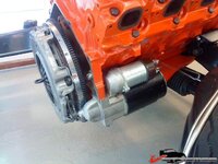
On to the flywheel and clutch.
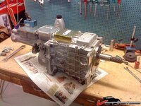
I ordered a SFI certified flywheel when i bought the Tremec TKO 600 gearbox together with a heavy duty clutch.
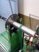
The flywheeel is made in USA and it is a well known quality brand. The instruction said to check unbalance before assembly, even although it was already balanced. Shown by a big hole drilled in the flywheel.

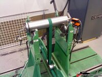
So, I started by measuring the complete flywheel in the digital measuring machine at my work.
With the guide diameter for the crankshaft as the reference surface, I measured runout of the inner diameter of the friction surface and the runout of the outer diameter (just below the starter ring gear) in relation to the guide diameter.
The result was quite shocking to me:shocking: The measuring machine showed a total runout of 0,002" (0,05mm) on both diameters in relation to the guide...
This means that the larger part of the mass on the flywheel is acting as an unbalance weight. This is really not an indication of high tech and quality in my world.
Of course, the unbalance is fixed by the balancing operation but it would be better to do a more accurate machining from the beginning.

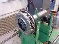
Well, I modified a balancing shaft that I had been using for snowmobile clutches with a small press fit to the flywheel guide diameter and balanced it to within approx. 0,1grams (0,00353 Ounces).

187750280e3d307b1.jpg
 
Tested the flywheel a couple of times and it showed an unbalance of approximately 5 grams (0,17637 Ounces). Not too bad! The unbalance was always in the same position which is good.
Drilled a few holes and tested a few times until I got it down to a steady 0,15-0,20grams (0,00529-0,00705 Ounces). Good enough for my engine at least.

187750281025e464c.jpg
 
Tested the clutch on the balanced flywheel and after testing it in all 6 positions,I could determine that the unbalance varied between 5-25 grams (0,176-0,882 Ounces), depending on position. Tested the clutch at the best position (5 grams unbalance) to see if the unbalance was at the same position but unfortunately, it moves around betwen every disassembly of the clutch... This is caused by the too large bolt holes in the clutch. The only solution is to drill guide pins to the clutch and flywheel. On this clutch that is not possible due to lack of space.
So, I marked the clutch-flywheel position so I can reassemble iton the engine later.

I will have to live with this 5 gram unbalance but what the heck, it worked nicely back in 69 without any balancing:amazed:

187750280e3dc52e1.jpg
 
Last edited:
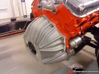
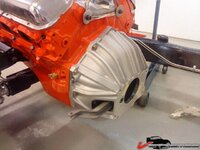
Cover installed. Spent quite a few hours checking/adjusting the run out of the housing guide hole for the TKO 600 according to the instructions.
Got it well below allowable tolerances so it should be fine.

187750280e3e59cfd.jpg

187750280e3e7aad5.jpg
 
As an Amazon Associate we earn from qualifying purchases. Product prices and availability are accurate as of the date/time indicated and are subject to change.
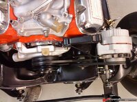
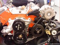
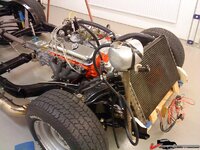
Did a trial fit of the generator and all the drive belts. The Power steering pump was really difficult to assemble, even with the body off. Extremely tight to get the bolts in place...

1877503a73265c850.jpg

1877503a7325bdb2a.jpg
 
The Radiator is not in final finish in the photo. I will fix that after start up. The fans are dual Spals and I will use an on/off switch to make them run during engine break in.

1877503a739a96e6b.jpg

1877503a739b069b8.jpg
 
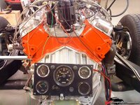
Built a control panel for the engine. It has a tach, oil pressure, water temp and volts. It also has an ignition switch and a starter button. All hooked up to the engine and ready for start up.

1877503a73262c2ef.jpg

1877503a7325effcc.jpg
 
Wiring a little sloppy, but gotta LOVE IT, that was much more major effort into that instrument panel than I would have done for similar circumstances.....

looks good enuff for a permanent install....

:nuts:
 
Wiring a little sloppy, but gotta LOVE IT, that was much more major effort into that instrument panel than I would have done for similar circumstances.....

looks good enuff for a permanent install....

:nuts:

Hope your joking Gene...
Damn this is 10 times better than what I did not long ago.
 
Wiring a little sloppy, but gotta LOVE IT, that was much more major effort into that instrument panel than I would have done for similar circumstances.....

looks good enuff for a permanent install....

:nuts:

Hope your joking Gene...
Damn this is 10 times better than what I did not long ago.

Just chewing butt, nothing I ain't done lots of.....pot/kettle.....

:nuts:
 
Well guys, I´m not very proud of the wiring:eek: I just want it all done now so I can fire it up.
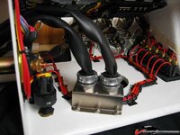
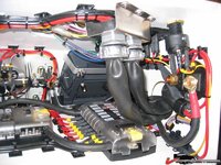
Spent a few more hours on my last project, a new instrument panel for my boat. This is the inside of it:lol:

1877503a835daea8f.jpg

1877503a835ddffd7.jpg
 
Have a question for you, as you can see I have the stainless ignition cables on the engine. They were bought new by the previous owner but I think the fit is terrible! The long cables are too long and the short cables ar too short, they are like guitarr cords over the valve covers. No possibility to fix it as I can see. Do anyone know if the ignition sets that you can buy from the large vendors, (Zip, CC), is of good quality or should I just by quality ignition cables and cut it myself to correct length? Any reccomendations on brand and so on??
 
Have a question for you, as you can see I have the stainless ignition cables on the engine. They were bought new by the previous owner but I think the fit is terrible! The long cables are too long and the short cables ar too short, they are like guitarr cords over the valve covers. No possibility to fix it as I can see. Do anyone know if the ignition sets that you can buy from the large vendors, (Zip, CC), is of good quality or should I just by quality ignition cables and cut it myself to correct length? Any reccomendations on brand and so on??

Bought a plug wire kit from Summit, the DIY kind, you get long cables, a set boot, a crippling tool and some dielectric grease.
With that you can setup you wire just like you want.
Mine goes horizontal from the plug to the firewall and then stright up to the dizzi. Cluter-free.
 
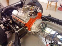
Finally started my 427 today:yahoo: Everything went well! Started immidiately and ran good. Did some adjustments on the ignition and then let it run for about 20-25 minutes at 2500rpm. I also varied the rpm up and down a bit during the break in.
Not a drip of oil, no vibrations, no overheating and no strange noices. I was really happy afterwards!
If you look at the left side of the car you can see the leafs blowing away from the sidepipe during the first seconds of the film.

I´m the guy with the hat backwards running around nervously...

[ame]http://www.youtube.com/watch?v=wElzdkNLPiw[/ame]
 
Last edited:
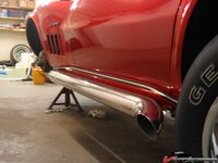
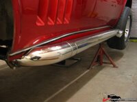
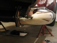
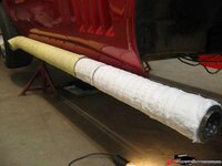
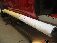
The sidepipes were welded by a guy I know. He´s a fantastic TIG welder, he even used protective gas on the inside to get a high quality backside of the weld. This will help avoid corrosion. Yep, stainless corrodes...

Anyway, after I got them I polished them and assembled them. Has been working fine for me. The inserts are "designed" by the welder. Nice sound, not too loud. I´m using a special high temp insulation that we use in our tempering ovens at work. Gives a low, deep tone.
They are 4" in diameter.

1877504cdc11d7503.jpg

1877504cdc11a40c1.jpg

1877504cdc116459d.jpg
 
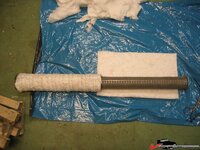
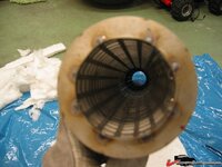
A few photos of the inserts.
The inner tube is made of a stainless sheet metal with holes in it, 10x10mm
Then there is a very fine stainless net over the sheet metal and then the insulation is wrapped around the pipe.
Inner dia. of the tube is 2,5".

1877504cdc1216ef6.jpg

1877504cdc124649d.jpg

1877504cdc1273b19.jpg
 
I can answer that one with actual numbers - yes, it goes from 600* to 400* to 265*

That is:
600 - straight pipe, no muffler
400 - muffler, no wrap

265 - wrapped muffler

I was curious as well, so when I did my side pipes I got my trusty temp gauge out. :)
 
SuperBuickGuy -
Thanks for sharing the data. That is incredible drop in temp. Still a burn on contact - but not like the Branding Iron! What product for the wrap did you use?

Any correspondence "real world" testing on a "jet hot" style coating? Inquiring Minds want to know.

Thanks - Jim
 
Back
Top