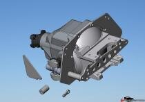
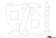
Six Link Rear Suspension

Starting to cut parts and Ohh oooo... Material thickness

This question is meant for Pier-Paolo , but please .....anyone can chime in. I had purchased plate stainless material and took to my cousins shop and was ready to be cut. Unfortunately we found out late it's thinner than the plans require.(don't trust anyone...measure it your self). Ok So plans call for 8 MM for outer 2 brackets and cross bar and 6 MM for the rest. As it turns out.... My sheets measure , 1/4 (6.35 MM) and 3/16 (4.75mm) . My delema is can I substitute the thinner 2 or should I double up as (Pablo did) the 4.75 mm for the outer bracket = 9.5mm ? That's the critical load bearing plate that the bearing hub bolts to. Is this over kill ? I'm not sure what the factory trailing arm thickness is? The projects on hold now :huh: Input.....
Thanks Grant :clobbered:
 
Last edited:
The configuration is a little different but the thickness of my offset arms is 1/4 inch. The material thickness of the stock arms is much less.
 
Sorry but I think that Grant is talking about the thikness of the TA in the area where the hub is bolted.
In this area the stock TA is some 3/8" thik.
For my opinion it is a good move to build this section with two layers of 3/16"..... its an area with lot of stress!
 
Progress..........

Thanks Pier & BBshark :
I'll have to do some shuffling but think I have enough material. One more thing.............. The later version of Pier's 6 link cad files has..... what looks like an extra cross bracket (w/ holes). Where does it go and what thickness should it be? Thanks Grant :cool:
 
Me Too...

I am in the process of having all of the material cut out of stainless for the 6-link. I will post pics in the future. I will be running an 80-82 aluminum batwing mounted to my iron 72 pumpkin (4.11 gear). Adjustible fiberglass (VBP) springs will also be mounted.
 
I am in the process of having all of the material cut out of stainless for the 6-link. I will post pics in the future. I will be running an 80-82 aluminum batwing mounted to my iron 72 pumpkin (4.11 gear). Adjustible fiberglass (VBP) springs will also be mounted.


New member...

Welcome to the motley crew of the Flying Dutchmen....

:D
 
-B file corrupted

Hi Guys,

I downloaded the files but the ultra-link-new-6mm-B.dxf file was corrupt. Does anybody have a full set?

TT are the files on the download link the latest version or is an update still in the works?

Thanx

Grampy
 
Tested the zip file, works fine. All files open just fine too. If still not working, let me know. It is the latest rev. I have.
 
"These are the cutting patterns to build your own Stroker-427 Design 6 link rear suspension.

These are not the final designs, some parts are missing. Will upload new files later (hopefully soon)
"

That sums it up! I'm gonna cut some card templates to see what fits and what doesn't.


NOTE: This set does not have the outlines - but the internal cuts/drill locations:


NOTE: This is what I believe those should look like when cut:


I will hopefully cut some card stock for fitment checks this weekend. I'll post followup pics after that, so we'll have an idea of whats - what.
(BTW - many thanks to Twin Turbo for hosting and posting!)

ANYBODY GOT PLANS FOR RACK AND PINION GEAR MOUNTS????

Cheers - Jim

NOTE __ I'll change the colors on the grey bolcks a little later so be easier to read -- but gotta go now :D
 
Last edited:
Well, The part I'm most interested in - The diff mounts are not there.

thum_12694aad7138106ef.jpg


There are 2 mini-batwings, but not the 2 plates for attaching to the diff.
If you want to do the new hub mounts and the mounts to replace the rear Trailing arms, it seems most (all?) are there. Oh Well, may have saved some card stock - but I may tackle the diff mount setup.

Cheers - Jim
 
Thank you all for your inovation, expertise and willingness to share!! This is a fantastic thread, and will be my next project for my car. A silly question though, as I look at the drawings, I don't see any dimensions. Obviously I'm missing something? I'd have to have these parts cut for me as I don't have the equipment in my garage. Even if I did, I'd still need dimesional drawings...or are these actual size templates?
 
A laser or waterjet cutter won't need the dimensions. All they really need are the lines in a .dxf or .dwg format.
 
The drawings are actual sized, the sizing and units are embedded in the document. As Larry said, just feed it into the machine and let er rip.

Here's the file you said is not working for you...I checked them again and again, they work fine here.
 

Attachments

  • ultra-link-new-8mm.dxf
    66.1 KB · Views: 102
I just opened it. I'm getting the outline of the parts.

It probably would be a good idea to print these drawings and put a couple of dimensions on the printed drawing. That will verify the scale to the cutter.

44ae1b8363cc9c.jpg
 
I see, I opened the docs, had to use Microsoft Viso to do it, but I can see all the parts. If I understand you correctly, you'd load the file into the controler of the appropriate laser, water jet etc. it reads the file (including references) and off it goes? Very nice, I'll be contacting a couple places here in JAX (that's all there are) to see if they can do it!!
 
David, That's really all you need to do. The cutter may want to re-arrainge the parts to fit the sheet they have but that is really all that needs to be done.

They could also do things like the serpentine brackets I sent to you. Let me know if you want to do that, I can email .dxf files to you.
 
Serpentine brackets? Do tell? I want to convert my camaro to serpentine.....interested!!!!
 
Larry,

That'd be great if you could send the bracket files, the bar stock I ordered should be here Monday and I found here in JAX that has a water jet and says they can do this kind of thing. If I can get the serpentine brackets mounted during the week, I can start putting the engine in next weekend.

One more question about the six link though...once everything is cut out, how do you locate the parts to weld them together???
 
still have a problem with -B file

Hi Guys,

I'm not sure why I have an issue but I downloaded the zip file again yesterday and I still get an error message "Invalid or incomplete DXF input -- drawing discarded" when I try to open the ultra-link-new-6mm-B.dxf file in AutoCAD. I also get junk when I just open the file in notepad - complete giborish. I have no problem with the other 2 files.

Anyone have a copy of the ultra-link-new-6mm-B.dxf file that is working for them that they can share?

Grampy
 
Grampy -
Try this one (I don't use AutoCAd) but did a conversion in Rhino in and out. Opened fine, saved and reopened ok too. Changed layers to BLACK - so it looks better on my screen.

Let me caution you. I zipped with 7Zip. But the VetMod forum wouldn't recognize it so I changed the file extension to 'Zip" so it would upload. Change the extension back to "7z" if it doesn't work as ZIP.

Feedback if it works and loads. Cheers - Jim
 

Attachments

  • 6mmB.zip
    12.6 KB · Views: 77
Top