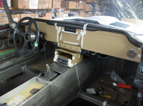
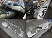
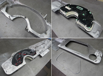
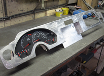
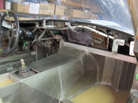
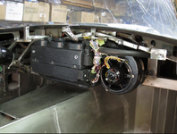
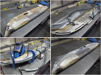
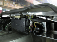
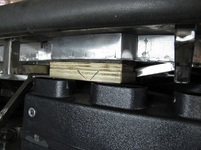
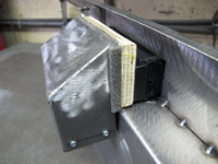
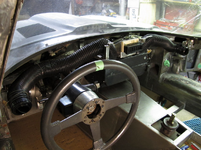
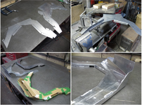
Amazing XKE Restomod - "Interior Panels" Update 2/12/23

BBShark

Garage Monkey
Staff member
Joined
Mar 5, 2008
Messages
4,671
Location
Right here
Door Skins

Chuck from Monocoque Metal Works says E-type doors are the bane of his existence. Fitting them to the body shell and getting the gaps correct can be quite a challenge.
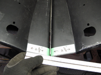
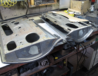
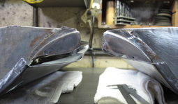
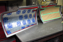
When it came time to installing my after market door skins on my repaired door shells, I could see something wasn't correct on the right side. After conducting a survey of the two, I found the one skin had the crease line stamped 1/4" lower than the other. My supplier in the States graciously offered to do an exchange, but considering shipping costs, I elected to hammer form a higher crease line to match the shell and the other skin.

Two door skins:
1669202579526.png

Measurement discrepancy, 2 5/8" VS 2 7/8"
1669202645157.png

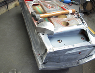
Shells siting on skins:
1669202731729.png

End view showing mismatch:
1669202816988.png

Had to shrink and stretch skin in various places:
1669202879033.png

Primed, painted and applied sound deadener at this time:
1669202950897.png

Installing skin, folded over edge with hammer and dolly:
1669203025764.png
 

BBShark

Garage Monkey
Staff member
Joined
Mar 5, 2008
Messages
4,671
Location
Right here
Setting Door Gaps

Apparently, when these cars were made in England, as the car body went down the assembly line, they would have a row of completed doors available, and would choose one that best fit the car in front of them. After mounting the door, they would lead in the body to fit the door.

Well, not in my case. Here it was a matter mostly of making the door fit the opening and doing some modifications to the body shell where needed.

With a good reliable door hinge, I was looking for a 1/8" to 3/16" door gap. With the doors mounted, there was very little length where I needed it. Adding or removing metal would fix it.

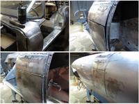
The left side bulkhead between the bonnet and the door was sitting proud of the door by more than 1/8". This could have been compensated for by adding filler to the door but that is never a good option. I opted to cut and section that area to bring it in line.

- first, remove the factory lead in the seam.
- second, cut and slice
- third, weld back together
- fourth, grind weld
1669203154051.png

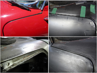
The upper front section of the E-type door has never appealed to me. The weather seal often doesn't sit right and a crisp, clean door gap is seldom achieved. I'm taking a chance on improving this.

- photo of red car shows weather seal mismatch
- set 1/8" rod in place
- weld rod to body
- finished door gap to 1/8"
1669203224825.png

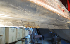
The gap at the bottom of both doors was too small. I took it to 1/8" by cutting back a 2" length, welding and grinding then moving ahead another 2". My pace ended up at 6"/ hour.

Example of one 2" length:
1669203288350.png

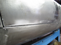
Finished door gap:
1669203347995.png
 

BBShark

Garage Monkey
Staff member
Joined
Mar 5, 2008
Messages
4,671
Location
Right here
Door Window Frame

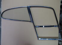
Fitting the window frame into the door shell is a matter of making it fit the best you can in the space you’re given. Much like getting the door shell to work with the hinges and latch mechanism, the door frame must work with what it comes in contact with. A lot of variance of fit can be taken up with the door seal that this car comes with, except for one area and that is the contact between the rear edge of the window frame to the ¼ window or rear side glass window. This is a double seal that requires a gap tolerance of 1/16”.

Keeping these two windows in that relationship really limits how much you can move things around.

The ¼ window attaches to a B post that mounts with a limited amount of adjustability, top and bottom.

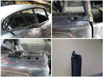
Using the rebuilt door shells and new door skins, I set about to try and make the window frame fit in the space with the correct gap to the ¼ window. It took a lot of study but I came to the conclusion that the mounting screws for the B post were never installed correctly from the factory to allow for a correct gap. This is especially critical since with the window being 24” long, a small angle changes the window position a lot. I knocked out the captive nuts and enlarged the two holes enough to move the B post to where I needed it. If it never fit properly before, it’s going to fit properly now.

Laid out, window frame and ¼ window relationship:
1669203617342.png

-¼ window installed
-lower mount
-enlarged holes
-B post seal
1669203694714.png

Installed correctly:
1669203773536.png
 

BBShark

Garage Monkey
Staff member
Joined
Mar 5, 2008
Messages
4,671
Location
Right here
Back To The Bonnet

Having taken care of two major areas of concern, the rear fenders and the doors, I returned to the bonnet. As previously documented, all the metal work repairs have been done, it's hinged and sitting well. But it's far from complete.

On the job list are covered headlight lenses. Out of curiosity, I spoke to the previous owner about the fact that the right fender had the Series I flanges to mount the lens yet the left fender and center section was straight cut metal, as if open headlights had been installed. He knew nothing of all that. Odd arrangement.

So starting from scratch, I needed to keep to a similar plan form to original for the lens and make both sides the same, mirror image. I got one chrome headlight trim ring with the car so from that and sizing up the opening that was there, both sides, I came up with a CAD piece to represent the flange I needed to fabricate.

My plan was to bend 3/16" rod to the shape needed then weld it to the opening edge. I would add a sheet metal flange, stepped down after that, to match a formed acrylic custom formed lens.

-CAD piece in place to trim metal
-3/16" rod bent and in place
-rod split at fender/center section
-shaped rod
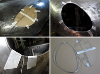
1671385242543.png

Welded in place:
1671385337838.png

Bonnet Assembly

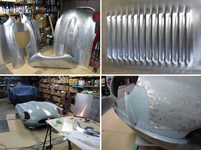
With all the metal work completed on the four bonnet panels, I was looking forward to finally getting it assembled. After a good cleaning, I sent it out to be epoxy primed.

I was willing to add a reasonable amount of filler where the panels join in order to get a smooth transition from one to the other. In order achieve this and still be able to separate the panels, I slipped thin sheets of aluminum between them. The flange surfaces were finishes as well.

-panels cleaned
-louvers=time
-work area
-panel dividers
1671385454664.png

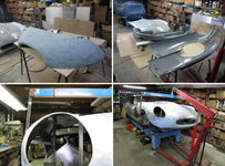
I also took this opportunity to final shape the lower valance. This would be very difficult to do while it's on the car and flipping the bonnet on its back is cumbersome.

All the flanges were epoxy primed again before final assembly.

I had to reconfigure my bonnet lift now that it was in one piece.

-shaping lower valance
-epoxy prime all mating surfaces
-bonnet lifting point
-bonnet on the move
1671385555526.png

Bonnet Splash Panels

With the bonnet assembled and on the car, I could now proceed with fabricating the inner splash panels. These needed to line up with the lower splash panels already mounted to the chassis. The 1/16" aluminum panels would be mounted to 20 gauge angle brackets attached to the bonnet underside with adhesive.

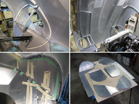
First step was to project up from the chassis panels and create a layout on the underside of the bonnet representing the placement of the bonnet panels. Along these lines, I cut cardboard, shaped to the bonnet and lining up with the chassis panels.

With these cardboard templates, I fabricated ¾" wide angle brackets with compound curves to match the shape of the bonnet. The compound curve required me to slice the one side of the angle and bend it inwards.

After test fitting the brackets to the bonnet, I fastened them to the panels temporarily then applied adhesive to the bonnet side of the bracket and secured it to the bonnet. Any discrepancies of fit would be taken up by the adhesive.

Originally, Jaguar fastened this type of bracket to the bonnet with a Sikaflex product. With some research within the Jaguar owner's community, I ended up using a 3M product, Marine Adhesive Sealant 5200.

With brackets attached, I drilled through the bracket/panel and used 3/16" blind rivets to assemble everything.

Please note: Particularly with these photo collages, click anywhere on the photo to blow it up to full size - in a new window. This new window can then be maximized for a still larger image.

-shaping angle brackets using shrinker/stretcher and slicing
-brackets next to cardboard template
-aluminum panel layout
-test fitting
1671385662846.png

1671385727819.png

1671385800451.png
 

BBShark

Garage Monkey
Staff member
Joined
Mar 5, 2008
Messages
4,671
Location
Right here
Sugar Scoops

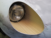
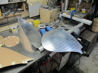
Vintage kitchen flour/sugar scoops looked remarkably like the sugar scoops Jaguar used to fill the space in the bonnet ahead of the headlights. It's obvious how this item acquired its name.

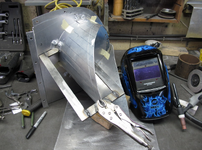
The bonnet I started with only had one scruffy scoop which was of little use to pattern off of so I would be starting from scratch. Aluminum was my choice of material.

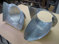
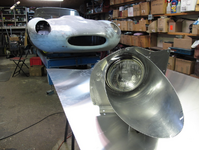
The basic design structure would be the curved scoop welded to a flat panel, bolted to the flanges on the inside of the bonnet. This flat panel would have a cut out to accept the headlight that would be mounted on its own flat panel. This would enable me to remove the headlight for servicing without disturbing the sugar scoop assembly.

Corrugated cardboard model in the bonnet:
1673181881398.png

Setting up curvature on flat panel:
1673181957796.png

Shaping by hand, second scoop on steel tube:
1673182035321.png

Test fitting before headlight cut out:
1673182138806.png

Welding L brackets to fasten scoop to panel:
1673182224779.png

Both right and left assemblies:
1673182299988.png

Ready for installation:
1673182370600.png
 

bobs77vet

Well-known member
Joined
Mar 27, 2008
Messages
2,122
Location
arlington va
I just had a time to scroll through this entire thread again and I am simply amazed at this build, what does that guy do for a living? When I grow up I want to be him.
 

BBShark

Garage Monkey
Staff member
Joined
Mar 5, 2008
Messages
4,671
Location
Right here
To go from where he started (a crusty hulk), to what looks better than new is impressive for sure.
 

BBShark

Garage Monkey
Staff member
Joined
Mar 5, 2008
Messages
4,671
Location
Right here
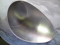
Headlight Lens Covers

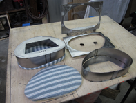
To fabricate my own lens covers, I'd first have to make a mold to form them off of.

My plan was to make the base of the mold from polystyrene rigid foam board then finish it with painted bondo.

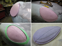
I started with a stepped piece of foam, supported from the back and shaped it to the headlight opening.

-rough cut
-shaping
-foam spaced inward
-foam mold

1673793135061.png

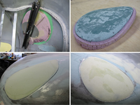
It was essential to support the mold from the back side to set it inward to allow for the bondo thickness. I started with the green fiberglass filler and finished with regular filler.

-backside support
-rough shape
-finished to meet metal headlight opening

1673793231427.png

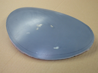
Final painted mold:
1673793324136.png

Forming Lens Covers

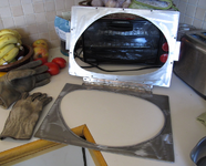
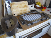
With some extensive research, I choose 3mm PETG as my material to form the lens covers from. I built a vacuum former, plans copied from others on the internet. It turned out to be very effective in shaping to the mold but I got way too much "mark off", imperfections from the painted mold, on the lens. I covered the mold with flannel but still had the imperfections.

After a phone call to a shop in California that fabricates canopies for aircraft, they suggested I try a drape form method instead of vacuum form. With some experimentation, I found a reduced time in the oven and concentrated pressure on the perimeter of the mold gave me a good shape and clarity.

In the end, a closely shaped blank, heated, dropped over the mold then pressed down with a perimeter press, worked. Using about 2 minutes in a 300 degree oven, was good.

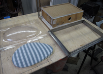
Vacuum former components:

1673793501123.png

Drape former components:
1673793622419.png

Drape former PETG hinged holder:

1673793717728.png

Drape former set-up:

1673793806681.png
 

BBShark

Garage Monkey
Staff member
Joined
Mar 5, 2008
Messages
4,671
Location
Right here
Finished Lens Covers

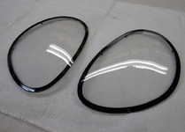
Lens cover flanges

Happy with the shape of the lens cover, I needed something to mount them to. At this point, all I had was an opening lined with 3/16" steel rod.

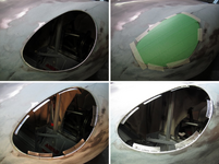
I started by setting the lens in the opening, flush with the outer surface of the bonnet. From the inside, I tacked strips of 20 ga. metal where the 6 mounting screws would go. The trick was allowing for the 1/8" gasket and getting the angle correct to match the lens.

After the 6 sections were in place, I just filled in the blanks, metal finished it, then drilled and welded 6/32" nuts on the back side.

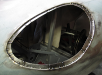
-lens opening
-lens set in place
-mount sections marked and tacked
-welded, mostly from back side

1673886931720.png

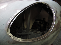
Filling in the voids:
1673886994481.png

Flange finished:
1673887158545.png

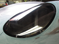
Finishing Lens Cover

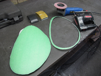
Final trimming of the lens was done with a jig saw and a disc sander.

To finish the lens, I painted the outside perimeter black on the inside. The fastening screws I choose were rather specific, described here:

"#6-32 Phillips Flat Head Machine Screws in Black Oxide 18-8 Stainless Steel featuring a 100-degree countersunk head are often used for shorter length fasteners to allow for a greater threaded length. 100-degree taper screws are often used when fastening thinner materials."

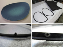
I cut gaskets from 1/8" neoprene and used contact cement, one side only, to glue it to the black painted side.

A small stack of heavier rubber rings went under the screws to allow more fastening pressure without distorting the lens shape.

The screw head counter sank successfully using a ¼" twist drill bit.

Trimming lens:
1673887247038.png

-marked and painted
-gaskets cut
-rubber spacers under screws
-counter sunk screws
1673887322139.png

Finished pair:
1673887394266.png

Lens installed:
1673887448536.png
 

BBShark

Garage Monkey
Staff member
Joined
Mar 5, 2008
Messages
4,671
Location
Right here
Prepping for interior work:

The last items to install while the car is still on the chassis table, are the two floor pans under the seats.
I'm holding off on these because with no floor, I can stand up in the car to do interior work such as dash fabrication, A/C controls and wiring. The car will stay where it is for now.

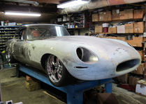
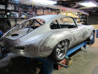
The car sitting on all four wheels, most of the body metal work is finished and some of the filler work is done on the bonnet.
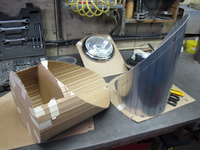
Here it is for now:
1675610145460.png

1675610197208.png

1675610267815.png

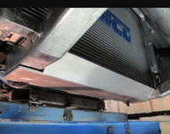
Skid plate

I added a skid plate, mostly to protect the steering rack mount which looked like a catch point on the underside.
It's made from ¼" aluminum backed by some ¾" square tubing.
1675610334640.png
1675610376427.png
 
  • Like
Reactions: rtj

BBShark

Garage Monkey
Staff member
Joined
Mar 5, 2008
Messages
4,671
Location
Right here
Interior

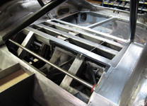
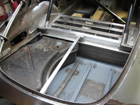
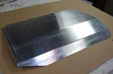
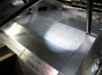
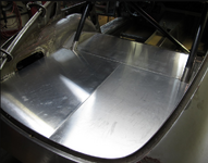
Independent rear suspension and boot panels

These panels were cut from 1/16" sheet aluminum. The section covering the IRS will be removable for brake servicing.
The panel on the driver's side in the boot area will be made removable for servicing the fuel tank while the passenger side will have some kind of a quick release arrangement.

Before:
1676210820817.png
1676210866177.png

Cut and bent panel:
1676210928063.png

Panels installed:
1676210989766.png
1676211029900.png
 
Top