rod70
Well-known member
I am humbled by the details in the Frankenstein thread, but here goes….
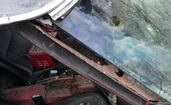
I found a chrome bumper Vette searching on Kijiji (Canada’s Craig’s List) and I knew nothing. This was my starter car. The ‘stalled project’ was advertised as a half finished 1970 complete with a rebuilt 350 in an adapted 1975 frame with new brake and gas lines and a partly sanded prime coat. There were other beautifully finished rods in another shed so I assumed this would be a safe start. What I quickly discovered was the adapted 75 frame was poorly measured as a shower of spacer washers hit the floor when I removed the rear bumpers. And forward was worse. The birdcage was rusted out from the top of the windshield through to the rear of the rockers. OK, this is a body off rebuild
The original 70 frame must have been pretty bad because what was welded to the back of the 75 frame was dilapidated. Cutting it free from the frame I started out by replacing the tank’s rear support with something a bit more substantial.

To support the true position for replacement, a 4 sided ‘box’ was built from scrap melamine and clamped on the frame centered over the body cushion nut keeper holes where I could run out measurements from. Absolutely straight kiln dried beams were clamped to the box and provided stability to spec.
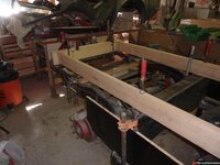

The empty space is the distance the previous ‘restorer’s’ guesstimate missed by.

The gaps were filled and ground and strengthening patches were overlaid.
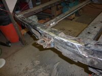
The frame was sent out for sandblasting and when it came back the paint that had made it look professional seemed to have been holding it together. Rust had eaten through the base in a number of places. I decided to replace the rust with new metal, cutting away and replacing one piece at a time.


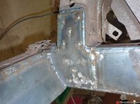
The corners were improved and extra internal bulkheads were added to help reduce the flex C3 Vettes seem to be famous for. At least 50% of the frame was replaced.
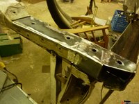
Spending so much effort on the rebuild, I got curious about suspension upgrades. Kijiji provided a complete 86 suspension including the front frame bolt-on tunable frame foundation with power steering intact.
The overwhelming issue is how to judge ride height for frame mounting positions. There was a further complication. Thanks to advise from a nephew with a speed shop, I bought a 100 lbs lighter LS 5.3 aluminum block. Providing ride height adjustability front and rear seemed a sensible strategy.
For the rear I decided to build a ‘ladder’ for the bat wing.
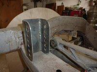
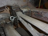
A matching ladder was made to house the struts inside a cut away frame. The ladder for the struts bracket would also allow me to play with anti squat if I found that important later on. The strut bolt-on plate was made from 3/8” steel. The holes were tapped and the nuts were welded on, threads in sync.
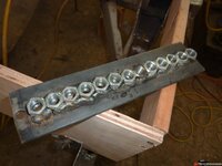
To lock in the strut bolt-on plate and keep it steady under stress, an internal side plate was fitted and welded to the ladder at 90° and around the wall.
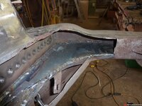
The street side edge of the bolt plate was welded to the inside of the original frame. To beef up the cut away area on the street side, an extra plate was cut and welded to the outside of the frame.
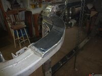
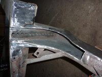
This new alignment required building new strut anchor brackets. Each bracket is held to the ladder with 3 bolts, and I expect some shimming may be required to bring things true.
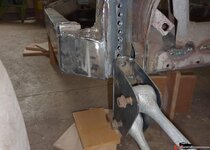
I also built an adjustable ladder mount for the differential.
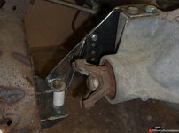
Up front for ride height, the front suspension was approached the same way but my logic was to cut up into the 70 frame to be able to drop it lower, if necessary, over the 86 suspension carriage. To bring the body and suspension into trim, I intend to insert high-density plastic thickness plates sandwiched between the 75 frame and the 86 carriage to adjust ride height. This approach was taken to maintain the whole front suspension system from the 86 as an intact self-contained unit.
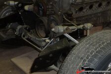
I didn‘t take an initial photo of the front suspension system so I hope these explanations will get us there. The 86 front suspension unit is an assembly line bolt-on piece also supplying the engine mounts. Angled mounting plates are eased back from vertical for quick nestling assembly, V into V. To have height adjustment, the first job was to replace the easement with vertical bolting ladders similar to my rear strut and batwing ladders, but this time bolting up double wide.
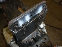
Next matching saddles to accept the suspension carriage were fabricated to be welded into the 70 frame. The height adjustment spacer plates will be horizontally sandwiched between these two and locked in with three joining frame bolts.
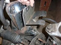
The front end was rebuilt with fresh metal and this cutaway shows the allowance provided for lowering the frame.
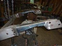
Internally extra heavy-wall rectangular reinforcement was prepared.

Saddles installed.
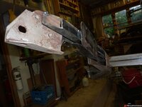

A bulkhead was added to lock in the reinforcement and the frame was closed in.
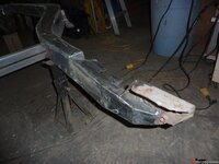
Fore and aft extra plating was added to the vertical side of the saddle and the open end was boxed in. Space for possible interference with the A arm was let in.

You can just see final angled upper boxing that integrates the saddles inside across to the outside edge of the frame.

From the side.
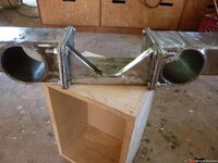
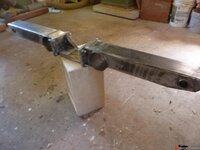
To further weld in frame stiffness a new transmission mount was built from 3 x 4 rectangular tube with a removable centre section. The centre sides were bottomed outwards 3° off so it could drop out easily. The ends have tubes let in for snaking gas and brake lines.
http://www.vettemod.com/forum/imagehosting
/273854bdb84c04eb2.jpg
Frame clearance with Vette 04 rims with 265 - R40’s. Width wise there should be at least 1/2” of clearance inside the wheel wells, hopefully not needing to add flares.

The engine needed a permanent position, free of the height adjustable suspension system, so the engine mounting brackets were cleaned off the 86 suspension unit and new ones were welded to the 75 frame supporting 01 fluid-filled cup engine isolators. I also added an additional under engine frame support to reduce front flex and also as a buffer for obstacles nearing the oil pan.
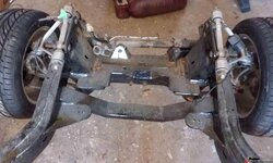
As yet, I have to provide for the shocks and anti sway bars, but I want to drop the body on with engine in to see how opportunities line up first.
I found a chrome bumper Vette searching on Kijiji (Canada’s Craig’s List) and I knew nothing. This was my starter car. The ‘stalled project’ was advertised as a half finished 1970 complete with a rebuilt 350 in an adapted 1975 frame with new brake and gas lines and a partly sanded prime coat. There were other beautifully finished rods in another shed so I assumed this would be a safe start. What I quickly discovered was the adapted 75 frame was poorly measured as a shower of spacer washers hit the floor when I removed the rear bumpers. And forward was worse. The birdcage was rusted out from the top of the windshield through to the rear of the rockers. OK, this is a body off rebuild

The original 70 frame must have been pretty bad because what was welded to the back of the 75 frame was dilapidated. Cutting it free from the frame I started out by replacing the tank’s rear support with something a bit more substantial.

To support the true position for replacement, a 4 sided ‘box’ was built from scrap melamine and clamped on the frame centered over the body cushion nut keeper holes where I could run out measurements from. Absolutely straight kiln dried beams were clamped to the box and provided stability to spec.


The empty space is the distance the previous ‘restorer’s’ guesstimate missed by.

The gaps were filled and ground and strengthening patches were overlaid.

The frame was sent out for sandblasting and when it came back the paint that had made it look professional seemed to have been holding it together. Rust had eaten through the base in a number of places. I decided to replace the rust with new metal, cutting away and replacing one piece at a time.


The corners were improved and extra internal bulkheads were added to help reduce the flex C3 Vettes seem to be famous for. At least 50% of the frame was replaced.


Spending so much effort on the rebuild, I got curious about suspension upgrades. Kijiji provided a complete 86 suspension including the front frame bolt-on tunable frame foundation with power steering intact.
The overwhelming issue is how to judge ride height for frame mounting positions. There was a further complication. Thanks to advise from a nephew with a speed shop, I bought a 100 lbs lighter LS 5.3 aluminum block. Providing ride height adjustability front and rear seemed a sensible strategy.
For the rear I decided to build a ‘ladder’ for the bat wing.


A matching ladder was made to house the struts inside a cut away frame. The ladder for the struts bracket would also allow me to play with anti squat if I found that important later on. The strut bolt-on plate was made from 3/8” steel. The holes were tapped and the nuts were welded on, threads in sync.

To lock in the strut bolt-on plate and keep it steady under stress, an internal side plate was fitted and welded to the ladder at 90° and around the wall.

The street side edge of the bolt plate was welded to the inside of the original frame. To beef up the cut away area on the street side, an extra plate was cut and welded to the outside of the frame.


This new alignment required building new strut anchor brackets. Each bracket is held to the ladder with 3 bolts, and I expect some shimming may be required to bring things true.

I also built an adjustable ladder mount for the differential.

Up front for ride height, the front suspension was approached the same way but my logic was to cut up into the 70 frame to be able to drop it lower, if necessary, over the 86 suspension carriage. To bring the body and suspension into trim, I intend to insert high-density plastic thickness plates sandwiched between the 75 frame and the 86 carriage to adjust ride height. This approach was taken to maintain the whole front suspension system from the 86 as an intact self-contained unit.
I didn‘t take an initial photo of the front suspension system so I hope these explanations will get us there. The 86 front suspension unit is an assembly line bolt-on piece also supplying the engine mounts. Angled mounting plates are eased back from vertical for quick nestling assembly, V into V. To have height adjustment, the first job was to replace the easement with vertical bolting ladders similar to my rear strut and batwing ladders, but this time bolting up double wide.

Next matching saddles to accept the suspension carriage were fabricated to be welded into the 70 frame. The height adjustment spacer plates will be horizontally sandwiched between these two and locked in with three joining frame bolts.

The front end was rebuilt with fresh metal and this cutaway shows the allowance provided for lowering the frame.

Internally extra heavy-wall rectangular reinforcement was prepared.

Saddles installed.


A bulkhead was added to lock in the reinforcement and the frame was closed in.

Fore and aft extra plating was added to the vertical side of the saddle and the open end was boxed in. Space for possible interference with the A arm was let in.

You can just see final angled upper boxing that integrates the saddles inside across to the outside edge of the frame.

From the side.

To further weld in frame stiffness a new transmission mount was built from 3 x 4 rectangular tube with a removable centre section. The centre sides were bottomed outwards 3° off so it could drop out easily. The ends have tubes let in for snaking gas and brake lines.


http://www.vettemod.com/forum/imagehosting
/273854bdb84c04eb2.jpg
Frame clearance with Vette 04 rims with 265 - R40’s. Width wise there should be at least 1/2” of clearance inside the wheel wells, hopefully not needing to add flares.

The engine needed a permanent position, free of the height adjustable suspension system, so the engine mounting brackets were cleaned off the 86 suspension unit and new ones were welded to the 75 frame supporting 01 fluid-filled cup engine isolators. I also added an additional under engine frame support to reduce front flex and also as a buffer for obstacles nearing the oil pan.

As yet, I have to provide for the shocks and anti sway bars, but I want to drop the body on with engine in to see how opportunities line up first.
