The VetteMOD project

It's a buddies car, not mine. You honestly don't think I would install steeroids on mine :crylol:
 
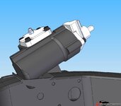
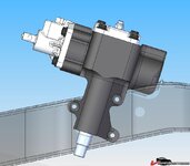
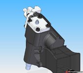
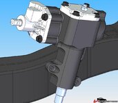
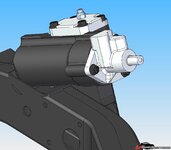
Here are some updated pics of my Jeep box setup. This would maintain all the stock steering geometry, use the stock mounting holes and use the stock pitman arm. The steering column would be shifted to the left about 1/8" but would be in the stock location vertically. The steering shaft would be pushed back in the column like all the other setups out there. However it uses a custom gearbox housing and a shortened pitman shaft. And the frame would need to be notched and reinforced as shown.

I'm looking for comments, advice and constructive criticism. If you guys don't come up with any fatal flaws my next step will be to actually buy a Jeep box (I've been working from Jim Shea's drawings) and create a model to get a housing CNC machined. You guys think a billet aluminum housing would be strong enough to hold up? Of course I haven't seen the inside of the Jeep box yet. There may be something in there that would preclude using aluminum.

Anyway, I value you guys opinions so let me know what you think.

82121.jpg


14502.jpg


76323.jpg


43584.jpg
 
Looks great. Why have a housing CNC machined? Why not have the housing milled down so you weld on a fabricated sleeve with the 3 mounting points. There's another company that does exactly that.

That model is awesome, very detailed. Do you have it with the stock mounting pattern also? I think earlier in the thread it had the 4 holes?
 
The cnc'd box would end up making it too expensive

I would just do it like norval
 
Last edited:
Thanks for the comments Marck. I have considered welding on a mounting sleeve like you mentioned however I have several concerns. First I am worried about the strength of the weld. I am certainly no welding expert however I have had cast iron welded before and it always cracked - this was years ago and it could just be the way it was welded.

Second, I think machining a new housing out of aluminum might be easier than cutting off the housing, machining a mounting sleeve out of steel, getting the sleeve positioned on the housing correctly and then welding it. If I get it machined out of aluminum I will simplify my model to make it easier to be machined. And, of course, I think it would be kinda cool to have a billet gearbox housing. :)

But I still might end up going with the welded sleeve option. I'm still undecided and may change my mind depending on what you guys think.

I do still have the model of the stock Jeep housing which I'll email to you. I also did some overlays of my modified housing with the stock Jeep housing. The first shows the pitman arm in the same plane and axis on both models.

68785.jpg


6.jpg


You can see that it gets the housing off the frame but creates issues with the steering column.

The second shows the steering shaft in the same steering and pitman shaft both in the same axis. This might work if you used a offset pitman arm to get the drag link back up where it belongs. You would need to weld a plate in your frame similiar to what Norval did for the different mounting hole location. And you would still need to notch the frame like I did with my modified housing.

8.jpg


7.jpg
 
I wouldn't be so concerned about keeping the Jeep box at the same angle as the Vette box. The joint you use can make up for the slight angle and rotating the box puts the pitman arm where it needs to be.

Also wouldn't cut that notch in the frame (even though you are boxing it back in). The motor mount is welded in the same place as the notch. Seems like a lot of hoops to jump through just to save the original mounting holes.

I'm going to guess at this but I'll bet I'm pretty accurate:

Aluminum billet $250
Machine/set up time 30hrs

Your probably looking at $3000 for the machined housing.
 
Actually it does matter, the pitman shaft axis has to match that of the idler arm, otherwise the pitman arm and the idler arm, combined with the center link don't form a symmetrical trapezoid. This will result in weird ackerman effects (a difference left and right with turning in and out)
The box height isn't as much as an issue, you can always use a bent (Z) pitman arm if needed to get the pitman arm tie rod end (hole) at the correct height. It would probably be best to play with it such that you are left with an acceptavle steering column angle. I don't see how notching the frame poses a big issue, just plate up the underside of the motor mount and gusset the front and the raer as much as the box will allow.

I agree on the original holes though, given the amount of work needed for the notch and all, it'd be easier to do what Norval did, fabricate a new mounting plate and weld that in place.
 
Actually it does matter, the pitman shaft axis has to match that of the idler arm, otherwise the pitman arm and the idler arm, combined with the center link don't form a symmetrical trapezoid. This will result in weird ackerman effects (a difference left and right with turning in and out)
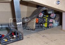
To fix the ackerman mismatch (which is marginal), the idler arm needs to be re mounted. This is probably the easiest mod to do on a Jeep box conversion.

Rotating the Jeep box and idler arm will improve bumpsteer over the stock stuff and keep the steering column from being rotated into your lap.
 
Yes, that's another option, changing the idler arm. However you want the angles to be such that the trapezoid when steering straight ahead roughly points to the rear axle center.
 
I'm tempted to just do the sandwich adapter

Seems to be working fine for the people who are using it

Arizonatrip165.jpg
 
This might be a little clearer. I did this once before by welding plates into the frame. It is very difficult to do correctly without the engine out. However I don't like the Swiss cheese mounting kit that is out there with all the adapter plates. So, thats the inspiration for what you see here.

I fixtured this as shown below. The jig represents the rectangular dimensions of the frame and the angle is the same as the frame section of the car.

I have a idea for an adapter that uses the original bolt holes and should be an easy bolt in. I do not have this idea represented here. I hope to have this information soon and I will post it here (at the greatest forum ever:1st:)with drawings. My design uses the 73-up A-body (Chevelle, El Camino, Lemans, Cutlass) pitman arm.

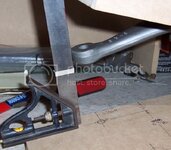
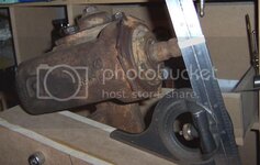
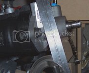
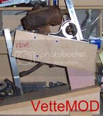
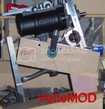
So here are the two mocked up, you can see that the Jeep pitman is slightly higher than the Vette (compare the 1/4 masking tape on the scale). This will actually improve bumpsteer so it stays were it's at. You can see also that the input of the Jeep box intersects the axis of the Vette box (compare the 1/4 masking tape on the scale). The scale is at the same position on the Jeep picture as the Vette. You can see how much longer it is.

I will post pix and drawings as I complete this.

Vette-overallcopy.jpg

Jeep-overallcopy.jpg

Vette-pitmancopy.jpg

Jeep-pitmancopy.jpg

Vette-inputcopy.jpg

Jeep-input1copy.jpg
 
great thread... 6 pages of really good info .... hard to find this type of quality information at "other places" :smash::smash:
 
Damn, it's been more than a month since I promised to do this. I have finally mocked up my Jeep steering gear. I hit kind of a snag with the 73-up A-body pitman arm. It seems that no one is really restoring these later Chevelles and so there is really no call for the pitman arms (making them very difficult to find).

I have changed my design to use the 68-72 PS A-body arm which is available and actually being reproduced.

For more information on this project, go to:

http://www.vettemod.com/forum/showthread.php?t=1098
 
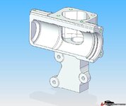
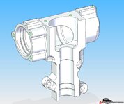
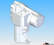
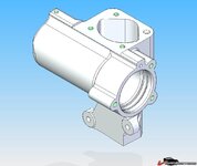
Finally an update. :trumpet: I have modeled up a gear housing that I plan to machine out of 6061-T6 billet aluminum and then hard-coat anodize. I'll also make a billet cover. I'm planning on shortening the Jeep pitman shaft and then machining the smaller Corvette splined taper on the end. Here are some pics.

5349596dd33c433.jpg

5349596dd412e11.jpg

5349596dd4d613b.jpg

5349596dd5af050.jpg

5349596dd679796.jpg

Comments/criticisms welcome.
 
NO offense to your engineers out there, but this amount of work and effort into a Jeep box somehow makes no sense to me, IMO, a rack is a much better and easier to attain project....

Once figgering out to use the Grand Am rack, the rest was simple, and if I can do it with a few trips to my welder friend across the river....surely the guys here can take my concepts and run with some tooling, I have some old drawings around somewhere, and see no reason this can't work on any shark or mid year for that matter....

THE PRIME difficulty is for someone wanting to DO this, is to do junkyard shopping.....that stops lotsa guys for some reason....

but I enjoy the hunt and free form thoughts and nice sunny days.....
usually best done alone, or with a similar like minded buddy to help with the heavy crap.....

wives not allowed......can't stand to hear the bitching....

:hissyfit::censored:
 
Very nice! I was concerned with the twisting force that is put into the frame with the Jeep box. The hydraulic cylinder on the drag link provides assist and the force is transferred to the other frame member. With the Jeep box, the servo is right on the input shaft and all twisting force is resisted by the driver side frame rail. So that means to me that the box and rail see more twisting force.

Not really sure what impact that will have long term but, if I were to change something in your design, it would be to make the three mounting lugs as strong as you can. That's the beauty of billet machining. The more material you leave, the stronger the part and less machining.

Is the internal machine work a bitch?

.
 
NO offense to your engineers out there, but this amount of work and effort into a Jeep box somehow makes no sense to me, IMO, a rack is a much better and easier to attain project....

Once figgering out to use the Grand Am rack, the rest was simple, and if I can do it with a few trips to my welder friend across the river....surely the guys here can take my concepts and run with some tooling, I have some old drawings around somewhere, and see no reason this can't work on any shark or mid year for that matter....

THE PRIME difficulty is for someone wanting to DO this, is to do junkyard shopping.....that stops lotsa guys for some reason....

but I enjoy the hunt and free form thoughts and nice sunny days.....
usually best done alone, or with a similar like minded buddy to help with the heavy crap.....

wives not allowed......can't stand to hear the bitching....

:hissyfit::censored:
You don't get it Gene. This was fun for me, not work. I really enjoy modeling things in CAD. And right now, in the middle of a midwestern winter; a trip to the junk yard doesn't sound like much fun. :eek:

This setup should be as light and rigid and tight as any rack setup I've seen. You need to make brackets to mount the rack and if you make them as robust as they need to be (unlike Steeroids), you've negated most if not all weight savings. I won't need to worry about oil pan clearance (I'm running the large capacity LT-1 pan) or reduced ground clearance; both issues with a rack. Also, I know I won't have clearance issues with my side pipes and headers. Nor will I need to be concerned with multiple u-joints (I know you only needed one) and all the issues with the steering shaft binding.

I'm not putting down all the other methods to improve C2 and C3 steering; I'm just exploring to see if there isn't something better.
 
Very nice! I was concerned with the twisting force that is put into the frame with the Jeep box. The hydraulic cylinder on the drag link provides assist and the force is transferred to the other frame member. With the Jeep box, the servo is right on the input shaft and all twisting force is resisted by the driver side frame rail. So that means to me that the box and rail see more twisting force.

Not really sure what impact that will have long term but, if I were to change something in your design, it would be to make the three mounting lugs as strong as you can. That's the beauty of billet machining. The more material you leave, the stronger the part and less machining.

Is the internal machine work a bitch?

.
Thanks for the comments. I'm not too concerned about the force on the frame. The manual box exerts the same force in the same area.

I may beef it up in some areas. It would be nice to have a FEA done on it. I know a guy that has the software. I might see if he would be willing to run an analysis.

The internal machining isn't too bad. Here are some cross sections.

53495a0b9c27c1e.jpg

53495a0b9ceb110.jpg

53495a0b9da1d29.jpg

53495a0b9e5d758.jpg

:drink:
 
The twisting force on the frame is quite a bit less on a manual steering gear vs. a servo assisted gear (Jeep).

The internal machine work looks pretty straight forward. Get some pix!

.
 

Latest posts

Back
Top