Simple wiring question

greg75vette

The Traffic Baron
Joined
Jun 9, 2009
Messages
704
Location
Lindenhurst, LI, NY
Hey guys. After a long hiatus due to personal conflicts (good and bad), I'm finally back working on my vette after almost a year. I'm making progress on the LS1/T56 swap, but one of the biggest issues I have currently is wiring. Very much the elephant in the room for me.

One of my hold ups, and I have searched a great deal to no avail, is how to use the new starter and alternator on the old C3 wiring. I can't seem to figure out which wire goes where.
Basically what I'm missing is what does each wire for the alternator and starter do on a stock C3 harness? I can't seem to locate a wiring diagram with this info.

Does anyone have a wiring diagram that shows this or knows off hand? I've been literally searching for this and the LS1 wiring info for about a year and haven't had any luck. It seems most people just know what goes where, but I just don't have a clue. :waxer::noob:

Any help would be great.
 
:facepalm: Completely forgot about that section...:banghead: Well, I do have similar wiring diagrams for the '75, but it was lacking some of the follow up pages that included the starter. The '74 diagram has these extra pages and might be just have enough of what I need.

Thank you for pointing that out!
 
75 has a couple oddities.
75 OEM Alt
Bat=bat term on starter
#1=ign switched
#2=sense wire (bat)

To connect to CS Alt
Bat=Bat
#1="L"
#2="S"

75 Starter
Big term=red 10ga wire/fuselink , bat cable, small black wire/fuselink (ammeter)
Small term=purple start wire

Interlock
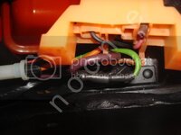
Cut the purple and green 10ga wires feeding interlock relay and solder together.

I appreciate the info, but I don't quite understand it.

-#2 on the alt, the sense wire; what does that do for the system?

-What is a 'CS' alt?

-What is interlock provide? Where does this green wire come from?

Sense wire tells the regulator to charge.
CS alt is the style that comes on a LS1 engine, that I assume you're going to use.
The interlock overrides the seatbelt safety cutoff. It's problematic, the relays are worth a bunch and best to just bypass it. The green comes from the neutral start switch. Relay is on the pass firewall with a button on the end for override.
If you are using a CS alt you may want to run another 10ga red parallel from the alt to the solenoid bat post to handle any potential amperage.
 
Ok, cool. That makes a lot more sense to me. All of this crap has been way over my head. Yes, I am using the LS1 alt, so CS it is then.

For the signal wire, I believe the computer already takes care of signaling for charging, but I will look into that.

I'll check to see if I can find that green wire on the firewall for override the system. I assume this would keep the car from starting without a seatbelt on or is it for the clutch depressed? If so, I know I could start the car previously with out the belt on, but needed the clutch depressed.

I think I will utilize part of the donor vehicles battery wire harness to connect the strarter and alt. Either that, or just run a new one. However, I should connect the alt to the solenoid, not the motor, itself? Regardless, positive to positive, right? Just double-checking.

Thanks again for the help. I think I almost have it!

Ok, I found what you were referring to with the interlock circuit. All I need to know now is which green wire to solder to the purple wire. Do I solder the purple to the light green entering the relay/override set or do I solder to the dark green coming out?

And completely forget that last paragraph in the previous post. It clicked in my head when trying to find the interlock on the diagram.
 
Ok, cool. That makes a lot more sense to me. All of this crap has been way over my head. Yes, I am using the LS1 alt, so CS it is then.

For the signal wire, I believe the computer already takes care of signaling for charging, but I will look into that.

I'll check to see if I can find that green wire on the firewall for override the system. I assume this would keep the car from starting without a seatbelt on or is it for the clutch depressed? If so, I know I could start the car previously with out the belt on, but needed the clutch depressed.

I think I will utilize part of the donor vehicles battery wire harness to connect the starter and alt. Either that, or just run a new one. However, I should connect the alt to the solenoid, not the motor, itself? Regardless, positive to positive, right? Just double-checking.

Thanks again for the help. I think I almost have it!

The computer has nothing to do with the alt charging.
The s term on the CS can be left off, but then the charge signal is at the alt batt term voltage. If you have high draw items like a big stereo, cooling fans or similar sometimes it's better to take the sense wire to that junction or harness.
If you don't use the original harness, you will loose the ammeter.
If running an extra 10ga, put a fusible link on it at the solenoid.
You defeat the interlock by simply unplugging the seat switches in the seat bottoms, but this interlock relay still has to work properly to juice the solenoid. They fail intermittently a lot, so it's just best to bypass them.
Green and purple 10ga wires. You can splice them behind the orange mount and reassemble, and even an NCRS judge will miss it.
Once you trace the wires, you'll get it. :clap:

Bypass1.jpg
 
Great pic! Thanks for that. I should be able to do that, no worries.

I already was looking into fusable links since it seems I would bypass the original harness link if I added a wire. Thank you for confirming it.


Now that I'm home, I decided to thumb through my build notebook and I found a couple of points I completely forgot about. As it turns out, my alternator only had two connections: the big charge cable and a "lamp line" connection to the regulator. The lamp line is supposed to be a 12V line, then an idiot light, then connected to the alternator regulator plug. It can't take 12V directly and either needs a lamp put in or a 500ohm resistor in series. I'll probably just hook up the resistor and call it a day.

EDIT: This is still a lamp line, but it DOES NOT need resistence. 98 F bodies need the resistence, 99-02 do not. In 99-02 alts, the resistence is taken care of by the ECU.

This greatly simplifies things. If only I remembered I had this little nugget sooner.

So to summarize:
-The new alternator get a the big charge cable (in the old harness) and a modified lamp regulator line (in the donor harness). To hell with all other wires :lol:
-Splice the green and purple wire at the interlock relay
-Install an additional 10g charge line from the alt to the starter solenoid with fueable link.

I need to look at the starter wiring a little closer, but with that new diagram in the tech section and fiddling with the wires, I should be able to figure it out. If not, I'll be back.

Thanks again 010752. Your advice has helped a lot.
 
Last edited:
Great pic! Thanks for that. I should be able to do that, no worries.

I already was looking into fusable links since it seems I would bypass the original harness link if I added a wire. Thank you for confirming it.


Now that I'm home, I decided to thumb through my build notebook and I found a couple of points I completely forgot about. As it turns out, my alternator only had two connections: the big charge cable and a "lamp line" connection to the regulator. The lamp line is supposed to be a 12V line, then an idiot light, then connected to the alternator regulator plug. It can't take 12V directly and either needs a lamp put in or a 500ohm resistor in series. I'll probably just hook up the resistor and call it a day.

This greatly simplifies things. If only I remembered I had this little nugget sooner.

So to summarize:
-The new alternator get a the big charge cable (in the old harness) and a modified lamp regulator line (in the donor harness). To hell with all other wires :lol:
-Splice the green and purple wire at the interlock relay
-Install an additional 10g charge line from the alt to the starter solenoid with fueable link.

I need to look at the starter wiring a little closer, but with that new diagram in the tech section and fiddling with the wires, I should be able to figure it out. If not, I'll be back.

Thanks again 010752. Your advice has helped a lot.

The 75 harness has the lamp line all set to go, no need for more resisters.
The #1 wire on the old alt goes to the "L" on the new alt.
On the starter solenoid you will have two 10ga red wires (1 original and 1 added) and the small black wire with the fusible link on the large terminal.
On the small terminal, you will have the purple wire.
 
Really? I didn't see it in the wiring diagrams and I don't recall there being a light for it. Well, having that line might help a little if it truly is there, haha. I'll have to check that out in the dash wiring.

Thank you for the tips on the starter wiring. I don;t know why this is so difficult to grasp for me. Wiring has always been the bane of my existence...

I do have one more question you. I was looking for more fusible links last night and I wanted to verify I should be getting a 10g. Should I be using a 10g fusible link or should I be using one of a smaller gauge, like 12g or 14g, so it is the weak link in line? Or is the design a 10g fusible link already meant to be the weak link in a 10g line?

Once again, Thank you so much for helping me out.
 
Ugh...:suicide: Turns out, I had the wrong info on my alternator. I DO NOT need to do anything fancy wiring wise. No resistor. 98 F body Alternators require the resistance. 99-02 F body alts do not. The one wire goes back to the ECU and is taken care of there.

So for the alt, All I need to do is plug in the donor harness plus, hook up the two 10g cables (one original, one new) and tape off the old wires on the harness. Done. Complete. Fogettaboutit.

Now I remember why this drove me nuts last year...

Regardless, I'll look into the starter crap and try to find the proper fusible link size for a 10g wire. 10g fusible links seem to be hard to find as well...
 
Top