Rookie's First Restoration Attempt...

Here is my powdercoating process...

1) degrease the parts
2) sandblast them
3) blow them off with compressed air
4) use wax and grease remover until the rag wipes off clean
5) place the parts in the oven to burn off any other oils I have missed
6) let the parts cool
7) apply powder
8) place in oven to cure

DSC02600.jpg

DSC02588.jpg

DSC02598.jpg

DSC02582.jpg

DSC02580.jpg

DSC02141.jpg

IMG_1943.jpg

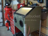
Here is the blast cabinet I made - I cut the wood panels at school and assembled it at home...it works great.

DSC02119.jpg
 
Some pics...I will post a writeup later on today with pics on how to press the bearings on the posi case and how to install the ring gear - I will also be rewriting my posi assembly tutorial for you guys - but first I need to get some rest before I head off to work in a couple of hours:lol:

DSC02726.jpg
 
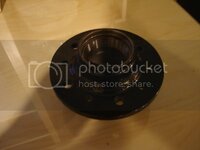
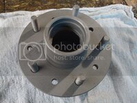
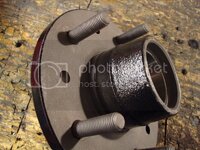
Okay, this is just a little update to get this thread rolling again. I still have a ton of photos and write ups to repost - including how to assemble the posi unit and install the housing bearings correctly by pressing them on all the way. The front suspension is done:D I finished it 10 minutes ago, sat back and stared at the frame for about 5 minutes...I am very proud of myself. I recently had found out that one of my hubs would not line up to the rotor - I think it was bent. I picked one up locally from forum member TGI-racing - he is a very nice guy. He only charged me 20 bucks, so it didn't cost me a whole lot. I punched out the races and sandblasted it. I left the lug studs in as they seemed to be in very good condition, and the last thing I wanted to do was %&ck these lugs studs up so they wouldn't realign again.

DSC02727.jpg

I then masked it of and powder coated the surfaces - I did not coat the face because it will affect the rotor runout. I originally had powder coated the inside faces of the rotor hats - I stripped that powder off very carefully because it was affecting the rotor runout. I also removed the powder coat from the face of the other hub on the front suspension.

DSC02729.jpg

DSC02730.jpg

Powder coated with new bearing races installed into hub.

DSC02731.jpg

DSC02732.jpg

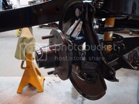
I then packed the bearings using mobil1 synthetic grease. I inserted the inner bearing into the hub, greased the oil seal and carefully pressed it on. I filled the cavity of the hub 80% full with grease and installed the small outer bearing in the hub and placed the entire assembly on the spindle, bent the cotter pin and installed my powder coated dust cap (did I mention that I am a perfectionist? I mean, who actually powder coats a dust cap; I'm such a retard:lol:)

DSC02739.jpg

DSC02744.jpg

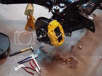
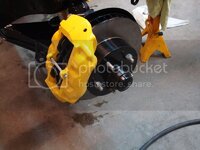
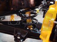
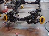
And here is the finished product. I think got the color combo dead on with the front end. The only things yellow are the calipers and the bilstein shocks. I will try and keep you guys updated the next couple of days - I've got to apply for university this upcoming year, and I will be pretty busy getting all that information together tomorrow and the next day.

DSC02748.jpg

DSC02746.jpg

DSC02747.jpg

DSC02745.jpg
 
Okay, here is that huge update I have been procrastinating on for the past week or so.

First I am going to start by rewriting my posi assembly tutorial - I found there were too many mistakes in the old one. I learned everything from Gary:thumbs:

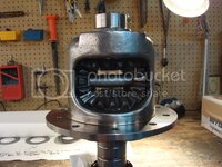
First, take your posi case and polish it using a carbide burr, dremel tool, sandpaper and any other tools you have which you think will work - you want all those rough edges gone, as this reduces stress cracks caused by all that torque put out by the motor. Polish the internal seems as well. Stay away from the area where the spider washers are; I use duct tape to protect these surfaces during polishing.

Here is what the case looked like before polishing...

DSC02248.jpg

After polishing for about 2.5 hours (only good pics I have are with it partially assembled)...
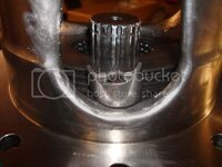
DSC02525.jpg

DSC02330.jpg

Look closely at the internal seams I polished in the back of the case...
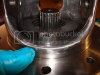
DSC02523.jpg

If you plan on using ARP ring gear bolts with your rebuild, now is the time to countersink the holes on you posi case. Gary touched base on this in one of his posts. Basically, what he found was there was a shoulder on the ARP bolts which prevented them from seating flat. The case I bought from Gary already had the holes countersunk, so that saved me from having to do it. A step drill might work to slightly countersink the holes too, but you'd have to ask Gary about that one.
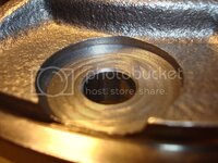
DSC02428.jpg

The next step is to bevel the edges on all of the gears in the posi case. I used a dremel grinding stone and walked it along the edge. The reason for this is because of the backlash you will be setting the case with. You want the case to turn smoothly after you are done - bringing the backlash on the gears to a minumum causes binding on the edges of the spiders. Remember, just walk the dremel - do not remove a lot of material.
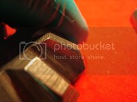
DSC02441.jpg

The next thing you want to check is the king pin that goes through the spider gears. I bought a used one from a vendor and found out it was worn:bs . I bought a new one from Gary - he sells an oversized one for the posi case. The OD of the pin should be 0.747 (I think that's what it is, I'd have to check). The ID of the holes in the posi case I think are 0.749. Gary sells an over sized cross-shaft with an OD of 0.748. Its a little bit of a tighter fit, which is a good thing. That's the one I used in my rebuild.

I clean everything with brake cleaner and compressed air. The next step is to sort out the clutches. They are stamped differently on each side. If you draw you fingernail around the edges, you'll immediately know which side has the deeper stamping. Take a sharpie and put a small "d" on the deeper face so you don't have to keep checking when assembling. The marker will eventually wear off from the oil, but it will keep you organized. I asked Gary as to whether it mattered which way the two clutch packs faced (do all the deep stampings for both sides need to face to the left, or to the right). He said it didn't matter, but you need to keep the deep faces facing in one direction for each clutch pack. Lay all your parts onto a clean rag - once again, this will keep you organized.
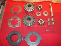
DSC02452.jpg

Alright, here is where all the patience on this project comes in - figuring out which size shim is required to set up the posi case. Here is a shot of all the shims that came in Gary's kit...
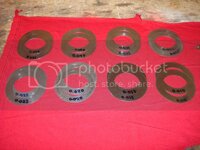
DSC02429.jpg

Start off with a 0.040 shim on each side of the casing. Chances are it is going to bind, but you've got to start somewhere, right? My definition of binding is that you turn the case and it turns, but you've got to apply a lot of pressure to get the spiders moving...I hope this makes sense. I have made of video of when I was originally setting up my spiders - this is what is considered extreme binding...

[ame=http://s6.photobucket.com/albums/y232/MGT-inator/?action=view&current=MOV02516.flv]th_MOV02516.jpg[/ame]

Once you install all the gears and shims in the casing, you want to seat the clutches. on each side. Do this by rotating the posi case about 50 times per side using the spanner wrench you made. When it comes to setting up the posi case - paience is a virtue. You need to get inside Gary's head and feel what he's feeling, it took me a really long time to understand what he was trying to explain to me. Lets say the 0.040 shims are too tight. The next thing you want to do is take those shims out and replace them with 0.035 shims. Seat the clutches again using your homemade spanner wrench. Next, take your bare hands and try rotating the posi case. Try it on one side, then flip it over and try it on the other side. If you are not able to turn the posi case by hand smoothly, then you need to try some 0.030 shims. Do exactly the same thing - seat the clutches, then try rotating each side using your bare hands. You want the feel to be smooth - you will feel a slight spider gear bumpiness, but it will be faint. If you don't feel a slight bumpiness, then that means the gears are now too loose. Basically, what this tells you is that the shims sizes you need are between 0.030 and 0.035. You need to figure out which shim for both sides is needed. They may be different sizes - it depends on the posi case.


So now you have figured out which size shims are too tight and which size shims are too loose. The next step is figuring out which size shim is needed on each side of the posi case. When I rebuilt my case, I found that a 0.035 shim on both sides felt a bit different (the side which is on the yokes is the one you are basically testing for tightness). With the ring gear side on the yoke, I turned it with my hands and found it to be pretty darn close to what I wanted; but when I flipped the casing over and tested the other side, I found it was a little bit tighter (but they were both 0.035 shims...so what gives?). This meant that the machining of the casing was a bit different on each side. Thus, the shim sizes were going to be different (so I only needed Gary to grind up one set of shims for me, both sides weren't going to be the same size). I had Gary grind me up one each of the following shims: 0.031, 0.032, 0.033, and 0.034. The shim I had in there was a 0.035 shim and that was a little bit too tight, so I swapped that one out for a 0.034 shim and tested both sides again. The feel of both sides now felt exactly the same. I left it at that. The final shims I used were a 0.034 shim and a 0.035 shim.

Will update more tonight
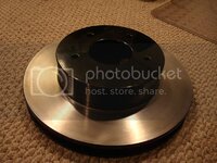
 
Got these parts in the mail a few days ago.

HD differential cover:

DSC02801.jpg

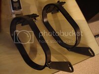
Half-shaft safety loops from Dragvette:

DSC02804.jpg

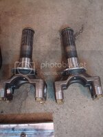
Lonestar HD hardened yokes with u-joint caps:

DSC02752.jpg
 
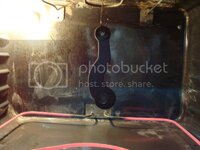
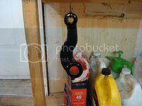
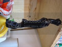
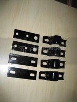
Just pulled this out of the oven - they are my half shaft safety loops from dragvette. I am waiting on parts, so I have been trying to keep myself busy. They were painted with regular spray paint when they came to me in the mail...now they are ring yellow powder coat.

DSC02855.jpg
 
Well guys, it looks like I did both good and bad today. I got all three bushing made for my steering box. I totally f*cked up my bushing which goes in the aluminum cover - I pressed it in the entire way, and now the pitman shaft won't sit flat at the bottom. There is a step at the bottom of the cover which you are not supposed to press past. I pressed the bushing in until it stopped - then I decided to give it one last tiny push to make sure it was seated correctly...then the bottom of the bushing gave way and got pressed into the entire cover! Looks like I pulled another Jeremy (AKA being a dumbass and going overboard with the press). The worst part about it was telling my friend that I messed it up (I was using the arbor press at his machine shop)...god that was embarrassing. He used a scraper to touch up the bottom of the bushing so the pitman shaft would go all the way in. We thought it had bottomed out and were good, but I measured it again when I got home and found it still had a long ways to go. I'm waiting to hear back from Gary as to whether he'll be able to machine me up a new bushing. Anyways, here are the pics of the new ones I properly installed and honed to 0.001 fit on the pitman shaft. I cut the grease grooves with a carbide burr on my dremel tool.

DSC02859.jpg

DSC02857.jpg

I think the OD of the original bushing was 1.250 - my friend made them to 1.252 so it was a tighter press fit. He then measured the OD of the pitman shaft - I think it was 1.220. He made the ID of the bushings 0.002 oversize (1.222'' ID of bushing). The reason for this is because the ID will shrink about 0.003'' when they are pressed in due to the larger OD. Shrinking 0.002'' because of the larger OD and 0.001'' because the original bushings were already snug. You will then hone the ID until the pitman shaft fits through the bushings (you use a brake cylinder hone for this). All pitman shafts and housings are different, so you may be chancing it by going off of my dimensions. Gary said that he has tried to machine bushings for people in the past, and they have had problems with them, so he doesn't do that anymore unless he hase the steering box right in front of him.

The material is 660 bronze (Gary uses oilite bronze). Oilite bronze has oil impregnated in the pores of the metal and it is constantly lubricated, you don't need the grease grooves for oilite.
 
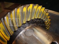
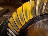
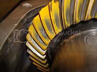
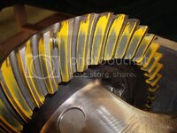
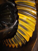
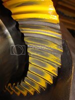
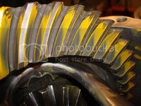
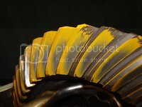
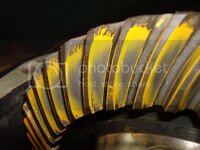
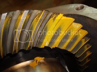
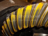
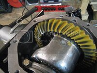
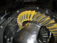
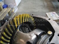
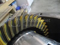
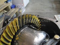
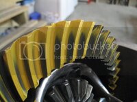
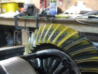
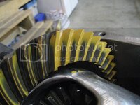
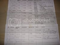
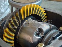
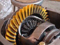
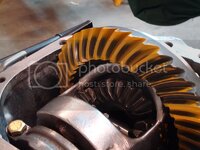
Here you go Gary - this was my first gear pattern and I am very excited. I still have to learn all the pattern tuning terminology, but this is a good start.

Pinion Shim: 0.026''
Pinion Drag: 17.5 in/lbs
Left Shims: 0.036''
Right Shims: 0.037''
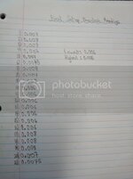
Backlash: 0.008''-0.0095''

DSC02915.jpg

DSC02914.jpg

DSC02913.jpg

DSC02912.jpg

DSC02911.jpg
 
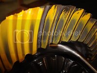
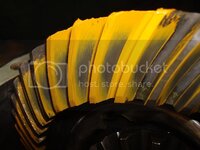
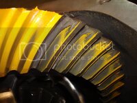
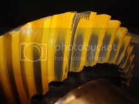
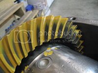
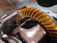
I'm taking baby steps - I reduced the backlash and did another pattern check. I think I need to increase the pinion shim size Gary?

Pinion Drag: 17.5 in/lbs
Left Shims: 0.038
Right Shims: 0.035
Backlash: 0.005-0.0065


DSC02916.jpg

DSC02917.jpg

DSC02918.jpg

DSC02919.jpg
 
Pinion Shim: 0.030
Pinion Drag: 17.5-18.5
Left Shims: 0.038
Right Shims: 0.035
Backlash: 0.005,0.005,0.006,0.0045

DSC02925.jpg

DSC02926.jpg

DSC02927.jpg

DSC02928.jpg

DSC02929.jpg
 
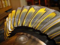
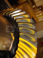
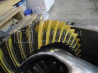
Okay Gary, I did a few things tonight. First I took my final good bearing and used it for the setup - my old one was giving me false readings with the torque wrench (which, by the way, is a great tool to add to my collection). I polished the black coating off the top of the pinion with very fine sandpaper. As expected, the new bearing gave very consistent reading with the torque wrench. I will need to get a new timken bearing from my bearing supplier on Monday. I increased the shim thickness even more so the carrier was a very snug fit in the housing - I can pull it out with my hands, but I have to work it out of the housing...it takes some effort). Anyways, here's the pattern with a 0.028 shim - I think I need to get a 0.027 shim ground to size, as my shims only come in 2 thou increments. I think I am close with the pattern now. I can see the end of the road with this diff rebuild:D

Pinion Shim: 0.028
Pinion Drag: 15-17 in/lbs
Left Shim: 0.038
Right Shim: 0.041
Backlash: 0.0065,0.007,0.008,0.0065,0.008,0.0065

DSC02930.jpg

DSC02931.jpg

DSC02932.jpg

DSC02933.jpg

DSC02934.jpg
 
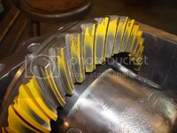
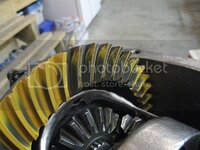
Tried the 0.026 shim again as I didn't have it a snug fit the last time I did it. What do you think?

Pinion Shim :
0.026
Drag: 17-18 in/lbs
Left Shims: 0.041
Right Shims: 0.038
Backlash: 0.005-0.008

DSC02936.jpg

DSC02938.jpg

DSC02939.jpg

DSC02940.jpg

DSC02942.jpg
 
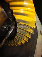
Installed the two new pinion bearings (the final good ones) and set the drag to 18-19 in/lbs. Did another pattern (still haven't installed the preload shims), and the fu*ker went deep in one area (couple of teeth). The backlash is lowest 0.006 and highest 0.0085. I'm not sure of what to do now - the majority of the teeth look good...so this may be the best I'll be able to get it. I'll wait too hear back from GTR1999 and tracdogg.
IMG_2288.jpg

IMG_2287.jpg

IMG_2286.jpg

IMG_2285.jpg

IMG_2284.jpg

IMG_2283.jpg

IMG_2282.jpg

IMG_2281.jpg

IMG_2280.jpg

IMG_2279.jpg

IMG_2278.jpg

IMG_2277.jpg
 
Jeremy,
This ofren happens when switching from the setup bearing to the final assembly. Gary and I go thru this on nearly every diff we do. Your pattern has gone deep in the root and moved to the toe. Here's your choices:
Open the backlash more not a good idea
Pull it back apart, change to a .024 or .025 shim. You might have to buy another bearing. best way
Run it as is. it will wear in but it will probably howl a little at light throttle when hot.
The biggest problem with the pattern is the pinion is touching the toe edge of the ring gear.
I highly recommemed you pull it back apart and install the .024 shim. Then adjust you final pattern with the backlash.
Mike


Most of the teeth seem to be good, the only ones which concern me are these ones...
IMG_2280.jpg

I have another brand new inner pinion bearing at home - I bought an extra one the other day in case something like this happened (which was a good idea). I only have a 0.024 shim. I don't care how long this takes me, I want to do it right...I've put too much time into this thing to have it howl just a little under low throttle. SHould I press off the bearing and install the 0.024 shim, or should I get a 0.025 shim ground to size?
 
This is what it has taken me to get to this point of the diff rebuild...

DSC02968.jpg

Not to mention how many damn cans of brake cleaner I have gone through:lol:
 
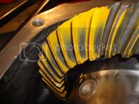
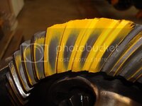
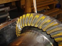
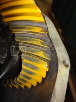
This is the last pattern I think - Gary and Mike just need to give me the okay, but everything is installed now and all I have left to do are the minor details (still have to fit side yokes, install socket cap screws, clean off the marking compound...)

pinion drag - 16-18.5
backlash - 0.006-0.008
DSC02972.jpg


DSC02997.jpg

DSC02991.jpg

DSC02988.jpg

DSC02984.jpg
 
Need to get myself a fill plug and two bottles of GM additive, but other than that, she is done.

DSC03028.jpg

Its been sitting like this since 12:00 last night, and no oil was leaking since I checked it last (a few hours after 12:00). Now I can start reinstalling the rear suspension!
 
I haven't been able to update this thread in a while due to me being occupied with my diff paper, sleeping, working, working on the vette...you know...the usual. Anyways, here's what I have been working on the past few days.

I stripped my trailing arm bolts from Vansteel - made of chinese crap I assume, because I was using a brand new torque wrench, recently calibrated and everything. Anyways, I decided I wasn't happy with the bolt quality, so I took a different approach. I went out to my industrial fastener place, and picked myself up some 7/16''-20 6'' grade 8 bolts (the vendors are supplying grade 5). The reason I bought them so long was because when you use a die to extend threads on a bolt, the few threads after the ones the factory rolled on don't have lots of bite to them. I wanted to basically have a shank with a hex head from which I could work off of. Now, I realize that cut threads are not as strong as rolled threads, but I am using grade 8, instead of grade 5, which will compensate from the "weaker" threads. I used a hand-drill to drill the cotter pin holes. You only want to cut enough threads in the bolt so that the nut can clamp the trailing arm pocket...you don't want any threads inside the pocket, it is a pivot point and it will bite into the frame if you extend the threads too much. It takes some time, and I messed up a few bolts, but it works perfect now. Instead of torqueing them to 50 ft'lbs and risking stripping my new (better than any vendor) bolts, I did the following. I packed the shims in the trailing arms so that they were tight (hand to use a hammer to tap them in). Then I used two hand wrenches to tighten the nut as much as I could and until the cotter pin holes lined up with the slots. I used one old original castle nut, and a castle nut from my new tie rods (I'm upgrading to moog). This bolt is a pivot point, so as long as it is tight, you should be okay. Anti-seized the hell out of everything - there is no way this bolt is ever going to get stuck again now:devil:

DSC03078.jpg

DSC03077.jpg

DSC03076.jpg

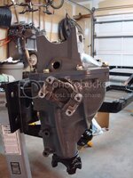
I then installed the crossmember on the differential. I talked to Mike (tracdogg2) yesterday on the phone about this, and he said its the easiest way to install it, so I followed his orders. After I mounted the crossmember, he told me to put RTV in the cushions so it creates a tight seal that moisture can't get into - I used some Loctite RTV sealant that my dad bought me, it works great...

DSC03034.jpg

Installed the differential all by myself (at 8:00 am...no one was around to help:eek:), I used my foot to pump the jack and supported the diff with my hands (never again I may add):laughing:

DSC03037.jpg

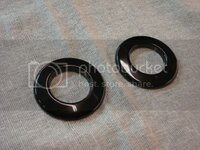
I cleaned out the sombrero holes beforehand using some q-tips and brake cleaner. A little bit of loctite on the bolts and then installed the aluminum disks my friend (he owns a machineshop) made me. It really stiffens up the crossmember.

DSC03083.jpg

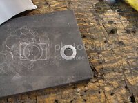
I couldn't figure for the life of me how the front differential bushing was supposed to be installed, so I gave Mike another call and he walked me through it. He told me to use my original thick washer that I took off the car, the wimpy one they sell in the kits it pathetic. I couldn't find the original one, so I sandblasted one of my old spring washers, then welded the hole shut (it was too big), and then drilled the center out for a 7/16'' bolt. I hate cheap parts, I really do...

DSC03094.jpg

DSC03039.jpg

DSC03093.jpg

I'll update more when I have some more time, and when I fix my half-shafts (I have to redo them). The diff paper is coming along great, and I plan on adding more to it sometime this weekend. I think its already 10 pages:surprised
 
Forgot to post this before. I think I stripped and then threw away my original fill plug from my old cover at the beginning of the rebuild (can't remember if I threw it out). Anyways, being in Canada and everything, I wasn't going to wait two weeks for a new fill plug to arrive. I also wasn't going to pay $9 for a damn plug, and then pay another $7 for a red posi tag (hell, I'll be the only one doing service on this vette, so no need for the red tag anyways). So, I went to home Depot and bought myself a 3/4 pipe plug. I brought it home, and used my bench grinder to slowly grind the 3/4'' mark which was on the head of the plug. Then I used my wire wheel to make it nice and shiny. I only paid $0.93, and it looks and works great!

DSC03097.jpg
 
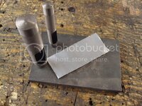
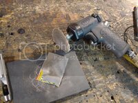
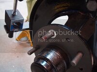
Finished the rotor runout on all four wheels using some aluminum from a pop can. If the material was too thick, then I used a surface prep tool to thin the "shim stock" down. I punches I used were 7/16'' and 3/4''. ). 0.003'' runout on the two front rotors. The rear rotors didn't even need shimming - they came in at 0.002 and 0.0025. Next time I'll be installing bolts like Gary does so the runout doesn't change - I'll have to buy some rotors with holes in them though. I have a nack for ruining new parts, and didn't want to mess anything up, so I left them just the way they were. Lots of people on here are running rotors just with lug nuts, so I'm not too worried.

DSC03101.jpg

DSC03105.jpg

DSC03103.jpg

DSC03104.jpg

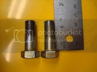
I also made myself the caliper mountign bolts. I originally uised a die to rethread a long bolt, but then I talked to Mike about it. He suggested not to use the bolt with cut threads, and to only do that in emergencies. The new one is on the right, and the old one is on the left.

DSC03107.jpg
 
Top