Rack and pinion - homemade Steeroids with GrandAm rack

50 lbs of metal for something that can be done better with 5 lbs of metal....judging that mine has not failed, YET....and looks solid as a rock, and the threads about steeroids and others? failing.....

I said I ordered some extra material ....
 
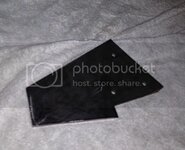
Ok, first piece is cut: the weight difference between 3/16" and 1/4" is not THAT significant but the stiffness and strength is :D

photo_zps06806402.jpg

The gussets are going to be 3/16" - just the main part is 1/4"
 
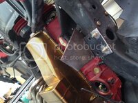
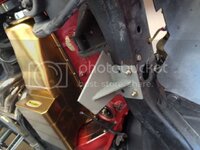
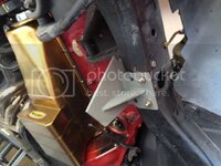
I think 1/4" was a good choice for the main plate. I bolted it in place, then cut the lower plate (the smaller one under the frame with the four holes) and once it was fitted and all bolted in place I tack wlded the two pieces, removed it, welded, added the gusset ..... Driver side is almost done....

photo_zps0da20ac9.jpg
.
photo_zps3a754412.jpg
.
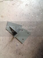
I hit the bracket with a sandpaper disc, then sprayed some self etching primer so that it doesn't rust.... When it's all done I'll sandblast all the pieces and use epoxy primer....
.

photo_zps45e62e96.jpg
.
.
.
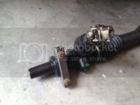
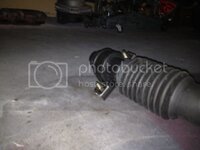
Ok, here's the rack with the 5/8-36 spline Flaming River U-joint and the diver side bracket.....

photo_zps805119d8.jpg
.

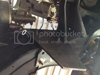
And the driver side bracket bolted to the frame

photo_zpsc1ccf039.jpg
.
 
Here's the plan for this week: I'll drill out the holes in the frame, the three holes that the long 4" bolts go thru, the three bolts that hold the main part of the bracket. The rearmost hole already has a tube inside the frame, I hope that hole is big enough for a 7/16" bolt, currently I'm using 3/8" Coarse thread, this is just during fitting this stuff, the final product will be held in place by three 7/16-20 fine thread bolts and lock nuts.... Plus four 3/8" coarse thread bolts on the underside of the frame.... Probably overkill but this stuff is what I'm going to use to steer the car, I consider it somewhat important.... :bounce::bump:

So the two foremost holes will be drilled and a steel tube welded to the frame - i don't want to take a chance and crush that frame when tightening the bolts :lol:
 
Looks good, speedway motors had good prices on all accessories. I used their threaded tie rods on my second hand steeroids set up.

You'll like the results.
 
Looking forward to get it down off the jackstands :D

Ok, today's progress: drilled the passenger side rubber bushing to 51mm (2"=50.80mm) to fit the larger diameter of the manual rack... My 2" hole saw worked quiet well :D

photo_zps8ec3dfac.jpg

.

Started on the passenger side bracket and I can really now see it come together.... This is going to be awesome.....

photo_zps664a3f5b.jpg

.
 
Since I had nothing better to do I started working on the templates and a second driver side bracket.... This one is 3/16" and it feels pretty solid once bolted in place.... I wonder what these vendors use to make their brackets... Sheetmetal ??? I think Marck commented at one time that the powdercoat seemed to be thicker than the steel that crap was made of..... :lol:

photo_zpsdf270f58.jpg

.

The 1" square tubing I'm using for the rack attachments and this center link is not the cheap shet from the hardware store.... It's actually .083" wall thickness so it's rocksolid....
.

photo_zpse0833999.jpg
 
You are going to raise the center link/bar much higher, than the rack traveler bolts, I assume......needs be about 4" higher at the inner tie rod ends....I made that error, and had the tie rods at the same elevation as the rack, and had a hell of a bump stear problem, one of the guys said to raise the tabs the tie rods went to....so they mount stud down/bolt on the bottom, keeping that pivot point high and that cut the bump steer to almost nothing.....


:gurney::drink:


Yup... here's one photo I found online, this is about what I'm going to do... not sure yet if I want to have the bolts vertical or horizontal.... bolts vertical allow for bump steer adjustment but limit the rod end movement a little....


rpcenter_zpsa2c0dd21.jpg
 
Something's dripping down there :D

Is the center bracket mounting pattern the same as on the power rack? Looks like it. I have a spare one from Speed Direct. Could come in handy sometime in the future if I convert to a manual rack setup.
 
You are going to raise the center link/bar much higher, than the rack traveler bolts, I assume......needs be about 4" higher at the inner tie rod ends....I made that error, and had the tie rods at the same elevation as the rack, and had a hell of a bump stear problem, one of the guys said to raise the tabs the tie rods went to....so they mount stud down/bolt on the bottom, keeping that pivot point high and that cut the bump steer to almost nothing.....


:gurney::drink:


Yup... here's one photo I found online, this is about what I'm going to do... not sure yet if I want to have the bolts vertical or horizontal.... bolts vertical allow for bump steer adjustment but limit the rod end movement a little....


rpcenter_zpsa2c0dd21.jpg

Due to the rack not being perfectly centered, and I forget just exactly why....maybe the steering input, maybe tire rubbing?? at any rate I have unequal tie rod lengths....19 and 21 inches as I recall.....

NOW, looking at your solution there, first off, I see Heim joints....I come back to that all the OEM makers use similar ball joint tie rod ends, and SO I don't trust heim joints....

then the other thought, as the wheels run up/down in a lean/turn, the push on the tie rods is rather multiplied with a long rod/strut in the picture above, and so will put too much force on the traveler/output block, twisting it in the rack slide, and forcing wear.....or failure....MY install was to just use longer tie rods, and surely maybe the handling was compromised, but methinks it takes a balls out racer to notice it....I think that long rod off the rack is a failure in the waiting....

:tth::flash::goodnight:
 
Something's dripping down there :D

Is the center bracket mounting pattern the same as on the power rack? Looks like it. I have a spare one from Speed Direct. Could come in handy sometime in the future if I convert to a manual rack setup.

NO - the power rack is longer than the manual rack and easier to mount. I just finished the passenger side bracket and my rubber clamp mount (stock Pontiac GrandAm or GM Cavalier) is located 4" off the frame towards the center.
The power rack mounting point could be 3" closer to the passenger side frame rail....
The driver side is identical.

Let me know if you want a set of brackets :D
 
Due to the rack not being perfectly centered, and I forget just exactly why....maybe the steering input, maybe tire rubbing?? at any rate I have unequal tie rod lengths....19 and 21 inches as I recall.....

NOW, looking at your solution there, first off, I see Heim joints....I come back to that all the OEM makers use similar ball joint tie rod ends, and SO I don't trust heim joints....

then the other thought, as the wheels run up/down in a lean/turn, the push on the tie rods is rather multiplied with a long rod/strut in the picture above, and so will put too much force on the traveler/output block, twisting it in the rack slide, and forcing wear.....or failure....MY install was to just use longer tie rods, and surely maybe the handling was compromised, but methinks it takes a balls out racer to notice it....I think that long rod off the rack is a failure in the waiting....

:tth::flash::goodnight:
The rack is not centered, you're correct. This is because of the unequal length of the rack...if that makes sense....here's what I did tonight: I turned the rack input shaft all the way from left to right, 3.8 turns..... Turned it 1.9 turns back and centered it..... Then I centered the inner tie rod bolts under the frame.... The driver side clamp is in line with my driver side bracket which is 1/4" thick.... Worked out perfect so far.

Now I have to rotate the rack so the the input shaft matches and is in line with the steering shaft.

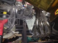
Many have cut the engine mount horn - I don't see why.... The frame horn does not interfere with the rack input shaft, at least not in a way that cutting the frame horn would improve the steering shaft alignment....

Gene, post a photo at roughly the same angle as the one I posted.....
 
Top