After many months rear suspension is ready for testing

daveL82

Well-known member
Joined
Apr 10, 2008
Messages
231
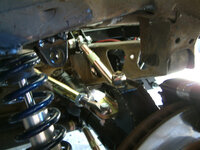
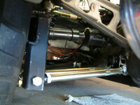
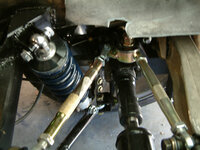
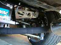
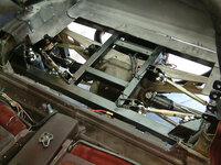
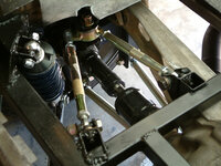
After many months of trial and error I'm finally ready to begin testing/debugging the rear suspension. I used some of the CAD images from here to locate the upper arm to reduce excessive camber change.

For the upper ball joint I used a mono ball and assembly normally used for front suspensions so we'll see how that holds up.
1241614686_J4eLG-M.jpg

1241614635_pAcHM-M.jpg

1241614687_mCQCH-M.jpg

1241614633_Dizb4-M.jpg

1241614632_NjKdr-M.jpg

1241614727_tBndc-M.jpg
 
Using my smartphone so a pain to post image links. Will to post some of the uprights this wkend
 
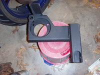
Here's an image of the bearing carrier before I added the upper bracket for the mono ball. The tab on top was driller for the 5/8 monoball the trimmed back after a fit check

It's made from 2x6 square 3/16 steel tube. The brackets for the mono ball locate the ball center in the same plane as a line drawn from the center lower pivot through the center of the u-joint. upper link runs parallel to the old half shaft configuration. It's about 1.5 inches above the top edge of half shaft.


484630763_WfMww-M.jpg
 
That looks GREAT! Any pics or details on the lower diff mounts? Dimensioned drawing would make it easy to replicate too. Nice work.
Hope to hear how it performs too.

Cheers - Jim
 
awsome. joined this site just to see these pics! 68 NJConv 454 on the "other" site. I think I like this site much better! Awsome setup you've got there, love to hear how it performs.

With full weight on the tires, how close is the upper ball joint to the frame?
 
Top