Amazing XKE Restomod- Wiring Complete and First Start 4/15/24

Yeah, I've been agonizing over fabrication of a plenum for my car for months.

I changed my mind when I saw this, apparently I'm just lazy:

1682369988091.png
 
Fuel Pump

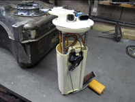
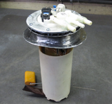
I wanted to use the fuel pump that I acquired with the engine/transmission package that I purchased. It's an original GM in tank unit with an integral swirl pot and pressure regulator.
The immediate issue I found, it was too tall to fit flush into the Jaguar fuel tank. I didn't want to modify the fuel pump assembly so I built an adapter to suit.

OEM fuel pump with level sender:
1683919624737.png

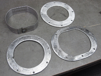
Parts fabricated for adapter:
1683919680671.png

The top ring holding the pump down, I was able to fabricate from aluminum:
1683919745036.png

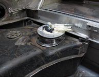
Because of an internal baffle in the fuel tank, I had to rotate the pump to provide clearance for the level gauge float to function. I used an angle fitting to route the hose.

Pump installed:
1683919815696.png

Air Intake

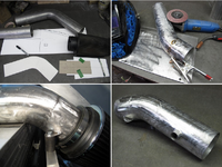
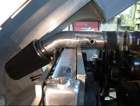
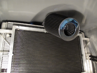
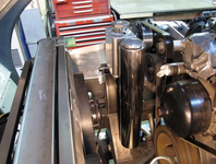
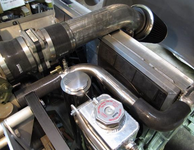
Thanks to the "power bulge" on the E-Type bonnet, I was able to get my air filter to the front side of the radiator in an easy manner. Space was tight but it did fit.

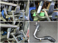
Using a 3 ½" diameter, 45 degree mandrel bent tube, I spliced together what I needed to get around the radiator and still clear the underside of the bonnet.

Added two ears that sit on the lord mounts and a bung for the AIT sensor.

Fabrication of the tubing:
1683920019323.png

1683920070838.png

1683920102314.png
 
Cooling System

Expansion and Overflow Tanks

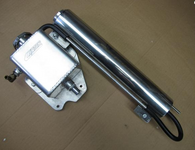
The dual pass radiator that I ended up with didn't have a radiator cap so I would need an expansion tank in my cooling system. This tank, from Canton, has a small line feeding into it from the top of the radiator and a 5/8" hose at the bottom of it that I choose to tap into the lower radiator hose with. This will be my fill point for the system.

The overflow tank is mounted next to the expansion tank, all on the right side of the engine.

Expansion and overflow tank assembly:

1692559807128.png

1692559845779.png


Lower Radiator Hose

Two things complicated the installation of the lower rad hose.

Firstly, the neck at the engine takes a 1 1/2" hose and the fitting at the rad takes a 1 3/4" hose size.
Secondly, the frame rail and the upper control arm obstructed the routing.

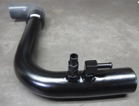
I collected the material to do the job being, 1 1/2" 90 degree and 1 3/4" 45 degree silicone hoses. A 1 3/4" to 1 1/2" reducer would take me to the 1 1/2" SS tubing I pieced together.

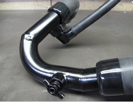
A bung on the backside of the tubing took a fitting for the 5/8" hose that goes up to the Canton expansion tank. A second bung lower down mounted the drain petcock since the radiator didn't have one.

Fabricating the SS tube assembly:

1692559918125.png

1692559967520.png

Heater Hoses +Upper Radiator Hose

I had to use a couple of 90 degree fittings to get the heater hoses going in the right direction. The 5/8" inlet hose has a shut off valve in line, controlled by the Vintage Air unit.

Hoses heading towards firewall:

1692560039833.png

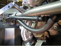
The upper radiator hose was much easier to route than the lower hose. Again, using 1 ½" SS tubing, I came out of the radiator but needed a 1 ½" to 1 ¼" reducer for the GM water pump neck. They have to make it difficult.

I added a fitting for a bleed valve and a fitting to connect the cylinder head steam pipe. Where to run this steam pipe is of some interest. Some people tap into the top of the water pump, others to the radiator.

Upper radiator hose test fitted:

1692560114994.png

Hose assembly with bleed valve and steam pipe fitting:
1692560188879.png
 
I'm going to redo the cooling system in my C3 as part of its EFI updates... love seeing how you folks are doing yours, it really helps envision where I need to go.
 
A/C Lines

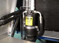
Space was limited for routing the A/C lines to the front side of the radiator to connect the condenser and filter dryer.

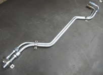
My only option was to use hard lines and sneak above the tie rod and below the radiator tank. I used two 24" lengths.

Hard lines shaped with fittings:
1695849848912.png

Lines installed and clipped:
1695849929884.png

Dryer mounted in front of radiator:

1695850010688.png

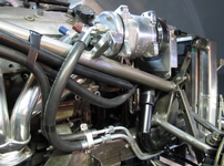
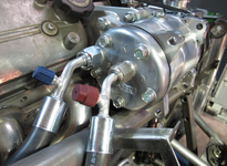
45 degree port fittings to exit compressor:
1695850095190.png
 
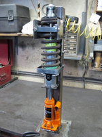
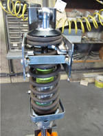
Coilover Spring Compressor

With the help of someone else's YouTube video, I put together a spring compressor to assemble and possibly swap over springs on my coilovers.

Works well:
1701682595451.png

1701682635616.png

I have the four original springs for the rear shocks which I'll mount and see how the car sits. That will give me a base line to work from.
I'll probably do the same for the front.

Backup Light

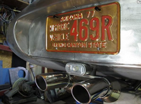
The Jaguar E-type used a single, centrally located backup light. I didn't get one with this car.
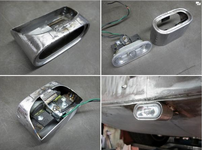
I liked the size and shape of the VW Jetta side marker light, so I went with that. After fabricating a housing, I mounted a top quality LED 1156 bulb in it.

Lens and housing:
1701682710518.png

1701682748100.png

Oil Pan

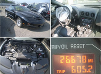
I bought the engine, transmission package for this car from a reputable dismantler out of Pennsylvania. The declared mileage was 26,678. I researched the car's VIN and found photos of the car in salvage, linked to the insurance claim. The photos showed the car was probably damaged just enough to write it off.

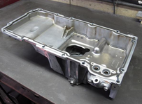
The engine turns over freely enough but I've never heard it run. If it isn't right, I'll have it fixed. In the mean time, I thought I'd pull the pan and have a look.

Car in salvage yard:
1701682825365.png
1701682879563.png
 
Steering Column & Coils
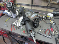
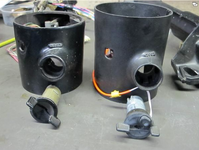
I wanted to use the ignition switch assembly that I got with the wiring harness/engine transmission package. That ignition key has the resistor in it that operates the Vehicle Anti-theft System. That switch assembly is a larger diameter than the one in the Fiero column I'm using.

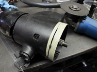
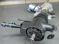
I was able to swap over the housing from the 2001 Trans Am to the 1985 Fiero column. The only modification required was to shorten the housing length.

Both columns disassembled:
1705254081610.png

Different housings and key assemblies:
1705254143863.png

Length being modified:
1705254205713.png

Steering column finished:
1705254276802.png

Ignition Coils and Wires

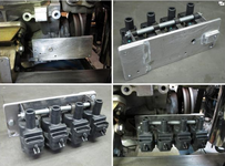
I've never been overly fond of the look the LS engine has when the coils are mounted on the valve covers. Yes, they're accessible for trouble shooting, but how often do they give you trouble? I choose down in front for this engine.

Mounting Coils

Right Side
I stacked the coils on a bracket fabricated from 20 ga. steel, then mounted that to an aluminum plate that bolts to the side of the engine block.
1705254384664.png

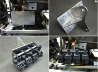
Left Side
Again, I stacked the coils, but here I mounted the aluminum plate to the front of the engine block, keeping the coils level.
1705254448558.png

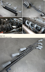
Ignition Wires

Left side
To keep the wires away from the exhaust headers, I ty-rapped them to a plate mounted against the block. The plates were made from SS sheet topped with high temp ABS plastic. I used an MSD wire kit that gives you the spark plug caps finished and then the coil cap ends are cut to length.
1705254601857.png

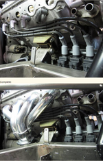
Wire rack mounted:
1705254698505.png
 
Wiring Harnesses

When I purchased the 2002 engine and transmission package, I had the supplier ship me not just the engine wiring harness but also the complete body wiring harnesses. I wanted to fabricate my own electrical system based on the OEM GM design.

The main harnesses in this car consisted of:
Engine wiring harness – more or less self-contained holding the PCM
Forward Lamp harness – located in the engine bay and has the two fuse blocks, upper and lower
Instrument Panel wiring harness – located mostly under the dash and has the I/P fuse block
Cross Car wiring harness – also under the dash, connecting the two doors

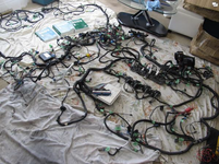
I laid out all four harnesses on the living room floor and took stock, labeling each connector to familiarize myself with what goes where. Initially, I must admit, I was overwhelmed with all the wires and connectors.
1712065489118.png

I put the engine and forward lamp harnesses in place to see if I could keep the PCM and the two U/H fuse blocks in the general vicinity of where they were in the Pontiac Trans Am. That would simplify the job of shortening and lengthening of wires.
1712065534909.png

The main systems I could eliminate to start with from the OEM harnesses were:
ABS - not applicable
DRL (daytime running lights) - not applicable
Stereo – using my own
Power Windows - using my own
HVAC - using my own

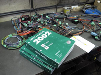
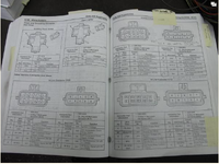
Using the 3 volume GM service manual, I plowed through each harness, adding and subtracting wires and connectors
1712065605242.png

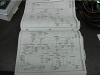
These manuals are indispensable. Learning how to use them takes time though. The two main features are the schematics showing wire size, colour, number and function.
1712065805192.png

The connector end views are useful for initial identification and later for wire location on the connector.
1712065672490.png

One step at a time

Wipers, final test

When I bench tested my Jaguar wiper motor with the GM wiper switch using my two relays, I thought that system was complete. But to be sure, I wanted to see them working in the car, with the new wiring harness.

The wiring harness was OK, but my switch selection was not. For the bench test, I used the wiper switch from an'85 Fiero. In the steering column I'm using, I have a switch from a '94 Firebird. They're not all the same. A simple swap would not work.

The solution was to take the internal parts from the older switch and transplant them into the newer switch body.

Replacing the battery in my iPhone 6 was easier.
 
Thanks!
Once again a you have provided me a "next step forward."
I like the spring compressor idea, and the fuel tank mod, and... on and on.

Cheers - Jim
 
Ignition Coil Control Wires

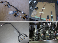
With the ignition coils relocated from on top of the valve covers to the lower sides of the engine block, it was obvious I would have to rewire their control circuits.
The original sub-harness was a compact unit that contained three spliced circuits and one control wire for each coil.
Using new wire, I fabricated two new harnesses.

In the photo:
-original harness
-fabrication, completion and installation
1713188775656.png

More metal work

Found some more metal work to be done during the wiring phase.

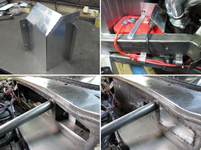
Fabricated a heat shield for the battery and shaped some clips to secure the battery cables to the frame rails.

Also filled the firewall. I was going to wait until I pulled the engine but I wanted a final harness pass through to work with. Looking for a "smooth" firewall.

In the photo:
-Aluminum heat shield fabricated
-Battery cables clipped to frame
-Firewall filled
1713188828788.png

Choice of connectors in wiring harness

For those unfamiliar with weatherproof connectors in the automotive field, there two types, Metri-pack and Weather pack.
Metri-Pack terminals are different from Weather Pack terminals in that the male terminals have flat tabs, similar to a quick-disconnect, rather than Weather Pack's round pins.

Since the GM harness that I'm using has the Metri-pack style, I chose to stick with them.
In researching Aptiv's products, (formerly Delphi), I found the GT series to my liking.
From the internet:
Aptiv GT 150 Connectors have a small package size suited to fit the shrinking space requirements of today's vehicles and equipment. Tangless terminals with stamped serrations, Connector Position Assurance (CPA), Terminal Position Assurance (TPA), and Primary Lock Reinforcement (PLR) with positive connector seal retention make Aptiv's GT 150 connectors easy to install and durable in heavy duty environments.

Mouser Electronics of Canada helped me choose the connectors I needed. It's a huge global distributor that ships out of Texas, quickly.

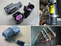
In the photo:
- example of a 2 pin GT 150 connector
- 4 pin connector for the A/C trinary switch
- 6 pin connector for the wiper motor
- wiper circuit relays bundled and labeled
1713188884760.png

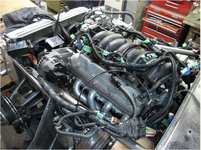
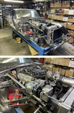
Engine running after first start

After a lot of work deleting circuits, adding circuits and testing circuits, I was ready to try and start the engine. It cranked but wouldn't fire.

Turned out, when I shortened the wires to the crank sensor, I didn't re-pin it correctly. Easily fixed, I was on my way.

Having never heard the engine run, I was a bit apprehensive, but I'm pleased with the results. I've had it up to operating temperature, there are no trouble codes and I'm happy with the exhaust note.
1713189004033.png

 
Top