Raising diff--any tips?

JPhil

Huh?
Joined
Mar 26, 2008
Messages
1,361
Location
Loveland, Colorado, USA
I'm going to raise my differential by removing the rubber mount bracket bushings. I've read the Herb Adams and Dick Guldstrand articles about it, does anyone have any tips or advice before I tear into it?
 
if you plate over the holes remember to measure twice before you drill the center mounting holes, and don`t forget to raise the pinion mount.
 
I'm going to raise my differential by removing the rubber mount bracket bushings. I've read the Herb Adams and Dick Guldstrand articles about it, does anyone have any tips or advice before I tear into it?

Really? Herb Adams & Dick Guldstrand? I didn't anyone besides John Greenwood recommended doing that.
 
If you do this, post some pictures. Thanks
 
I'm going to raise my differential by removing the rubber mount bracket bushings. I've read the Herb Adams and Dick Guldstrand articles about it, does anyone have any tips or advice before I tear into it?

Really? Herb Adams & Dick Guldstrand? I didn't anyone besides John Greenwood recommended doing that.

Greenwood (not Adams, sorry) in the VIP, & Guldstrand mentions it but gives no details.
 
I haven't taken anything apart yet but one thing worries me a little. They say to machine the discs with a 23/32" hole, then bolt them up into the crossmember and tack weld on the car. Then take it out and finish welding.

23/32" hole? that's almost 3/4 of an inch. Why so big? The bolts aren't that big at all, what 7/16, 1/2"?

I don't think I can tack them while on the car. My welding skills--and antique Hobart stick machine--are too rusty for me to try it, I don't know anyone with a portable I can bribe to come over and do it, and I can't use my friends shop rack for as long as it would take to do the whole job.

Would something like pounding in shims, or even (forgive me!) using a couple dabs of JB weld work to locate the plates so I can take the bracket to a shop for welding?
 
Would the crossmember be welded and a solid mount for the pinion mount? Seems like the welded crossmember would have to be angled perfectly so all 3 points line up. I would be interested to know the pinion angle before you raise it.

As for the disks, if you weld the crossmember to the frame do you even need them?
 
Not going to weld the crossmember to the frame.

For the front diff pinion bushing, I guess I will just take out an equivalent amount to how much I raise the diff. It will probably be solid by then.

That makes me think though---How do you verify the angle of the diff is not changed by this, and correct it if it is changed?

I haven't gotten into it seriously yet, maybe this weekend. Still thinking it through.
 
I did some searching. Apparently someone sold solid disks (2) to replace each rubber bushing. No welding required. I found a thread where one guy made his own, to his own thickness.

Looks like bolt in if you go this route.
 
Not going to weld the crossmember to the frame.

For the front diff pinion bushing, I guess I will just take out an equivalent amount to how much I raise the diff. It will probably be solid by then.

That makes me think though---How do you verify the angle of the diff is not changed by this, and correct it if it is changed?

I haven't gotten into it seriously yet, maybe this weekend. Still thinking it through.

Are you talking about welding the disks to the crossmember? I thought they were aluminum.

It would be interesting to see the diff angle you have now. I'll bet it's 1 degree or less.
 
This whole topic of rear diff pinion angles, and trans heights/etc is a mystery to me, in that I know what you all are saying the angles need to be the same at each end.....

Some time ago, I pulled out the disc from the vibration damper on front of the diffy, and bolted it steel to steel.....and drove it for several months, nothing changed, ran normally, no vibration, same when I put the puck back in place some months ago.....

now why is it so critical?? seems that angle crap changes plenty with the whole diffy going up/down in a more normal RWD configuratioin, so the thing is outta alignment a bit...so what??

A friend here with a '98 S10 pickup 4.3 auto, some nitwits lowered the truck, and so the drive shaft was rebuilt once about two months ago, the thing lasted only 1.5 months.....it had those krazy double universals on both ends of the drive shaft....SO this time around we got junkyard parts and redid the back/rear springs to get the ass in the air, and we also got the driveshaft with NORMAL single universals on each end....same shit, bolted right in place of the POS we had in there, no binding/problems in either case....so WHY would GM put in double universals with that stupid locating pin in the middle on a simple S10 driveshaft, when the other S10 had a normal driveshaft??? and to boot this was a two piece drive shaft, forward section never involved....center bearing crap, also proven not needed by Chrysler on my old work trucks a 7' driveshaft with normal single cross shafts on each end......

WTF is going on???? anyone make any sense of this shit???:suicide::surrender:
 
Gents,

I don't often visit this forum but I have been going through this same procedure albeit slowly on my frame over the past few months. Let me relay some of my findings. Just to be clear, I am doing this with the body off the frame. Additionally, I am installing a tko600 at the same time.

* The dimensions for the whole in the disc 23/32 is a typo. I found this out the hard way, but ended up using it to some advantage in getting things lined up. The real hole size is like 7/16 if I recall correctly. Since the holes in my discs were too big, I decided to cut a square plate from 1/8 inch thick steel with the correct bolt hole size in it. By threading the bolt through the square plate, then through the disk with the larger hole, I was able to adjust the position and then tack weld the plate and disk to the crossmember..

* Getting it all lined up without the top hat bushings was difficult, because as mentioned earlier, since you are hard mounting the crossmember to the frame, you need to hard mount it at the correct pinion angle to make sure your driveline angles are correct. This means you are trying to tilt the unit and position it side to side, hold it and then weld it. If you can do all that at the same time, you are a better man than me. The trick I came up with to help me make it happen was to take an old top hat bushing (from old crossmember) and slice 2 quarter inch thick slices from it using a bandsaw. I could then put the slice of bushing in the crossmember and it would help hold the crossmember close to lined up side to side and still allow me to set the correct tilt using two hydraulic jacks (at the front and rear of differential).

* Since I am installing a tko600, I had to set my driveline angles. With the Tko 600, I found I had to significantly raise the front of the diff to get the angles correct. That leads to the next problem the VIP article does not mention. The front pinion mount for the differential which mounts the diff to the frame will no longer work due to the higher angle. For me, I ended up grinding off the bolt support plates, welding up the front hole and extending the bracket and then relocating the front hole to be where I needed it to be. I left enough room for a trimmed down mount between the bracket and the frame.

After I did the above, I decided to check clearances and we lowered the body onto the frame just to make sure it all worked. The combination of the raised diff and the angle I had to mount it at was very tight indeed. There was a slight gap left, but I decided to grind a tiny bit off the diff housing (reinforcing ridge, and only took like an eighth) to give better clearance.

I'm still in process and the above makes much more sense with pics, which I have, just not here. I'm happy to post but can't do it tonight.

Cheers.
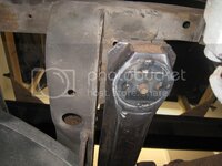
 
I'm not sure it raises the rear. Looking at the pics in the link you posted there is one which shows the crossmember laying on a flat surface, and it appears that the bushings and the diff mount are on the same level.

Cool looking stuff though.
 
Gents,

Below are pics from my car to illustrate the points above:

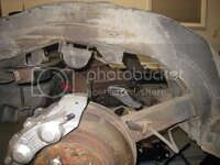
Here is the disc/plate setup tack welded in place. I tack welded the disc to the crossmember to get the angle correct, and then properly located the crossmember from side to side (sliding the bolt and the plate in the larger disc hole), then tack welded the plate to the disc. I still have to drop it and finish the welds. (I'm new at welding, so cut me some slack please!)

IMG_9620_zps28a861ca.jpg

Here you can see the mods necessary to the front pinion mount. Again, remember that I am installing the tko600 at the same time and had to set driveline angles. YMMV on this one as to how much you need to tilt the diff. I also let room for a cut down front mount to leave a small bit of play in the system.

IMG_9618_zps537045f2.jpg

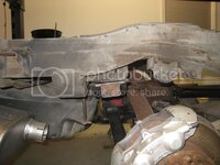
Here's one thing that has been bugging me about the project. With the tilt needed on the diff, the angle the crossmember sits at is not flush with the chassis mount points. This results in what you see below. I was planning on trying to go back and install some type of shim to distribute the pressure, but if you think about it, the force on the diff will try and make it rotate nose up, so filling in the space at the rear of the gap is really moot. It became even less of a point for me since I decided to go with a Vansteel coilover setup in the rear. That setup transfers the weight of the car to the wheels through the shock mounts, so the weight of the car is no longer transferred through this mount point shown below. I'm comfortable with the setup doing just fine holding the diff in place.

IMG_9619_zps498bee8e.jpg

Good luck on the mod. I found it has been challenging so far, but nothing too difficult. You just need to make sure you have all your ducks in a row and do a lot of mocking up.
 
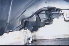
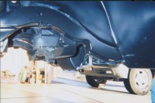
A while back I used a C-3 rear crossmember to put a C-3 (Tom's) differential in my C-1. I modified the ends of the crossmember to fit the C-1 frame, but I also modified the center to raise the differential. It was a little work, but it worked well. The car still has the C-3 differential, but it is now coupled to modified C-4 uprights and forward 4-link.

Rear Crossmember.jpg

Rear Crossmember 2.jpg
 
Well, more to it than I originally thought. That's to be expected, that's why I inquired. Thanks all!

I think this may go on the back burner for a little while, I have a lot of other things on my plate plus good weather is finally arriving so I want to drive the car while I can instead of tearing it apart again.

One more thing though, does anyone have some good photos of the diff mount bracket and frame by themselves? I can't remember exactly what it looks like in there and the assembly manual only has a small drawing.

One more question: Might it not be a better way to go by notching the crossmember to raise the diff and leave the mounting of it alone?
 
Last edited:
JPhil, your last question pre-empted my planned post.

I wanted to leave the rubber bushings in place, but I have lowered the car and wanted to get my driveshaft anges back.

So I notched the crossmember and raised the diff by 3/4".

I haven't addressed the pinion angles yet, but have been driving the car for a few months and have no issues so far; except the best handling I have acheived with the car yet, especially phenomenal and predictive in the wet.

Good luck with whichever route you take.
 
My thought was to cut & re-weld the front diff bracket to leave the stock front bushing as well, leaving all the stock bushings in place for flex needs, just relocating the diff.
 
Top