C5 rear toe link length?

69427

The Artist formerly known as Turbo84
Joined
Mar 30, 2008
Messages
2,972
Location
Clinging to my guns and religion in KCMO.
I'm going to shorten the rear toe links on my '69 to cut down on the factory C4 suspension bump steer, and unless I can find another stock C4 part to modify I thought I might try using a pair of C5 units. Anyone know the length of the C5 links, and if the tie-rod end is similar in size and taper as the C4 ends?

Thanks for any help.
 
Sorry Mike, I'm no help here. However A C5 appears to have a wider track than a C4 so, I'm guessing, the toe control is longer. How does shortening the toe control rods cut down on bump steer?
 
Sorry Mike, I'm no help here. However A C5 appears to have a wider track than a C4 so, I'm guessing, the toe control is longer. How does shortening the toe control rods cut down on bump steer?

The stock C4 toe-rods are noticeably longer than the halfshafts. When the rear wheel moves up or down the halfshaft reduces the track width more than the longer toe-rod does. Essentially the center of the wheel moves inward with the halfshaft arc while the toe-rod end (attached to the rear portion of the wheel) does not move inward quite as far, causing noticeable toe-in on travel. Making the toe-rod length similar to the halfshaft length keeps the tire from toeing in excessively during travel. I'm just trying to reduce the toe-change to a minimum while still staying away from toe-out during cornering. I had a few decades of rear roll toe-out experience with the original C3 suspension and that was enough for me. :amused:
 
Well, I've got inquiries in four different forums, and hundreds of views, and minimal response. I'm coming to the conclusion that C5 guys either never look under their car, or they're just not that willing to help. I'm close to just posting the question to some sellers on ebay. The prospect of making some money off me might persuade someone to grab a tape measure and help me out.

A backup plan is to make my own links using tie rod ends. The only tie-rod ends I see that fit most Corvette knuckles of the last 15-20 years uses M14-1.5 female threads. But I'm not sure how to make the connecting link. I checked several places and getting M14-1.5 rod in a reasonable strength isn't easy. I could use tubing for the main body, and then just screw long studs into each end, but I still would need decent strength 14mm threaded material (and both RH and LH threads). So, I'm still looking.

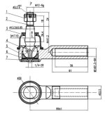
I kicked around the (preferred) idea of using SAE tie-rod ends and reaming the knuckle bores to fit the SAE ends (and then being able to use easily available and inexpensive DOM tubing from the speed shop catalogs), but I can't find parts descriptions of the tapered stud length. The Moog site shows the thread sizes and pitch, along with the stud taper, but not the length of the stud. The later Corvette ends seem to have longer studs as they fit into aluminum knuckles rather than the previous steel arms/knuckles. (Maybe I'll get back on Moog's website and see if there's a place to ask for additional technical info about their products.)

Any help or advice is welcomed.
 
The ES2908RL for the C4 rear OTRE has the dimensions shown in the attachment. Don't any info for the C5 or C6.
 

Attachments

  • ES2908RL.jpg
    ES2908RL.jpg
    47.4 KB · Views: 12
The ES2908RL for the C4 rear OTRE has the dimensions shown in the attachment. Don't any info for the C5 or C6.

Hey thanks, man. I appreciate it. From what I've been able to dig up I believe the C4s and C5s share the same tie-rod part number. I've been trying (unsuccessfully) to get some info on the stud length for this part (2908), and the drawing you supplied has it.

Thanks again.
 
The ES2908RL for the C4 rear OTRE has the dimensions shown in the attachment. Don't any info for the C5 or C6.

Welcome to the motley crew....

Start a new thread, as you are a newbie....and pix of your projects are welcome....

:trumpet::yahoo:
 
Picked up a pair of low mileage C6 toe links. Looks like they might work out. I want to sneak up on the process of reducing the rear toe steer so I'd like to initially make the links as long as they'll go, and then incrementally shorten them up as I get experience with the different geometry. So, my question is how far out can I unscrew the tie-rod ends. Does the old rule of matching the length of the thread engagement and the bolt diameter apply here? The inside toe link during cornering is under tension, but lightly loaded. The outside link is more heavily loaded, and in compression. I worry about the link bending if the thread engagement is slight, but I keep thinking that even with a large amount of engagement that the threaded area just inboard of the tie-rod end would see the same forces, so the bending issue is no different. (Remember, I'm just an electrical guy delving into areas I probably have no damn business getting into. :amused:)

I think I could mathematically come up with some info about this to help me sleep better at night by not having to worry about the link failing. I know the vehicle weight, and I can assume (for worst case calculations) a 50/50 weight distribution, and a 1 g cornering acceleration. I also can measure the distance rearward that the toe link is from the tire centerline. I'll give the calculations a try while I'm watching tv some evening.

My plans are to make a new bracket that bolts to the center of the batwing that the toe links will attach to. As I shorten the toe links to reduce the toe (in) steer I was just going to shim the pivot points outward, somewhat like shimming the front A-arms during an alignment.

So, what's the thoughts on the thread engagement?

Thanks,
Mike
 
I'm not sure what the inboard joint is on the toe control link but I assume it is a ball end like the outboard joint. Within normal range of motion the ball ends release the rotational degees of freedom on the link so no torsion or bending loads can be applied. Only tension and compression forces are considered. The tesile area of the male and female link components have been matched by the manufacturer so the only piece left is the strength of the shear area of the thread engagement (your question). Assuming equal stength of the male and female thread material the male thread shear area is smaller. Use the minor diameter of the male thread (google it) and calculate the area of the circle (tensile area). Then divide this area by the circumference of the minor diameter. The result is the length of the (thread) engagement cylinder with the same area. The allowable shear stress is traditionally one half of the allowable tensile stress so double the previously calculated length. This is the minimum length of engagement needed so the threaded connection is as strong as the link itself.

Grampy

Grampy

Okay, most of this sounds familiar, and I followed it all, with the exception of the bolded parts. If I divide the Area (Pi*D^2/4) by the Circumference (PI* D) I get D/4 for the thread engagement length (prior to the factoring in the accepted 50% shear strength rule). But I'm not following the (physics) reasons why to divide the area by the circumference.

I enjoy the flow of your technical writing. May I ask what your specialty/experience field is?

I appreciate your input on this topic. This is the only forum I post my "deeper" technical questions into. There's a broad experience and talent base on this forum that is not found in many other sites.
 
It just seemed the simplest way to explain the issue as I was composing it while being late to leave for my grand daughter's 3rd birthday party.

The tensile area (A = pi/4 * D**2 ) is the cross sectional area of the link. The critical parameter of the threaded joint is shear area of the thread root. The shear area is in the form of a cylinder so (A = pi * D * L). We need to solve for L. That gets us equal areas but we must increase the shear area to account for the lower shear allowable stress so double the length.

My undergrad is in Aerospace Engineering (yes, rocket science) PE in mechanical.

Happy to help where I can.

Grampy
 
Temporary detour.

Well, I'm in the middle of welding up a new bracket to attach the toe-links to the batwing cover. So far the biggest difficulty has been room to work. There's just enough room to sneak my hands between the batwing and the crossmember that the spare tire bucket hangs from. I'm working by braille pretty much as the crossmember hides the working area from my view. (It sure was easier messing with the suspension before I put the body back on.) I've been wanting to replace this crossmember with an aluminum part (and actually, the whole frame behind the batwing mount brackets). I have heard that later C3s don't have this crossmember, but that got me curious as to how the tire bucket is suspended.
So, I'm kicking around cutting the crossmember out, and short term making a small tubular crossmember that would bolt into the swaybar mounts immediately behind the crossmember. This would speed up the toe-rod installation and bracket fabrication.
I'm also thinking that this will give me better access to the frame area right behind the batwing mounts, and allow me to more easily cut the frame there when I want to weld up an aluminum replacement for that rear section.

So, two questions: Am I crazy for doing this, and what holds up the tire bucket in later C3s?

Thanks for the input,
Mike
 
Well, I didn't see any posts telling me not to cut the crossmember out, so in a bit it'll be gone. I have some temporary (thinwall) square tubing I can put in the swaybar area while I cut the crossmember out. I'll make another stronger temporary crossmember (before the next track day) when I get some thicker material.
Next trip to visit the relatives up north and I'll stop at my favorite scrap yard for some aluminum tubing. I can get stuff at "scrap + profit" prices rather than "new from the factory" prices.
I need to find a similar scrap yard here in the KC area.
 
Got the crossmember out (15#). Here's an ancient picture when I first got the suspension in (starting with a very soft spring).

IM001079.jpg

A few of the C4 toe-link bracket bolts are hidden behind the crossmember, and trying to mock up a new bracket without actually being able to see the link angles just got too frustrating, so the stock crossmember is history. I welded up a temporary crossmember (the surface-rusty looking thing) that bolts to the swaybar mounts. Once I get the toe bracket finished I'll weld up a "proper" bolt-in crossmember to tie the frame rails back together.


Making the new toe bracket ought to be a bit easier now.
 
It just seemed the simplest way to explain the issue as I was composing it while being late to leave for my grand daughter's 3rd birthday party.

The tensile area (A = pi/4 * D**2 ) is the cross sectional area of the link. The critical parameter of the threaded joint is shear area of the thread root. The shear area is in the form of a cylinder so (A = pi * D * L). We need to solve for L. That gets us equal areas but we must increase the shear area to account for the lower shear allowable stress so double the length.

My undergrad is in Aerospace Engineering (yes, rocket science) PE in mechanical.

Happy to help where I can.

Grampy

Okay, sorry for the delay responding back to this post, but (I believe) I finally figured out why the concept wasn't making sense to me. When you mentioned "cylinder" above I kept envisioning a solid round bar rather than a cylinder (my error!). So, things are quite a bit clearer now.

I went through the calculations and things appear to be workable. I set the toe links to the length I needed to get the desired geometry, and then measured how much engaged threads I had (.560"). I measured the bolt root diameter (.496"), giving an area of .193 square inches. Doing the calculations with a .496" diameter cylinder of .193 square inch area yields a length of .124 inches. Doubling that result yields a .248" length. The thread engagement I'm left with (.560") comes out to 226% of the calculated "minimum". So, it appears that I may be able (as a last resort) to tweak the alignment by the usual way of engaging more or less threads into the tie-rod end (although that would change the link length, which I prefer not to do). Hopefully I can get the new bracket dialed in close enough where I won't have to mess with the link length that much.
 
Sorry if my choice of words slowed you down. Maybe cylindical surface at thread root would have been clearer. Anyway, I'm happy you worked through that and are getting the geometry fixed.

Grampy
 
Real happy on how things worked out at the last track day. The rear was very stable and predictable (and nothing broke!).

IM002269_zps5a4f1d39.jpg

I made the bracket so I could shim the pivot point up or down, or shorten or lengthen the link length a touch if desired. The car handled nice and I don't feel a need to tweak it much at the moment.

I'm kicking around tweaking (reducing) the camber curve next. I don't know how to tweak these link lengths using stock GM parts (I like the looks of a stock suspension, but I'm not comfortable shortening and welding the stock strut rods) so I might have to consider some Heim joints and threaded tubing (assuming I don't find some alternate length links on a junkyard donor car).
 
Top