C3 Balance Bar

vette427sbc

Well-known member
Joined
Sep 25, 2008
Messages
1,034
Location
Jersey Shore
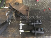
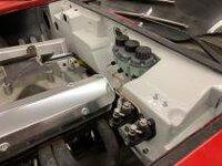
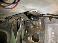
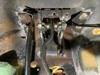
Next project for my '69 is to try to incorporate a Tilton balance bar into the stock(ish) pedal box area. There are balance bar setups that would be bolt in but I dont like that the whole assembly is outside of the firewall. The plan is to modify the pedal assembly to allow for the balance bar to attach direct to the pedal (like it should) and put two master cylinders on the firewall. Ill also be changing the stock manual ratio from 5.4:1 to 6:1.
As much as Id love to just buy a lightweight forged aluminum firewall mount pedal box from Tilton or the other companies out there, there are two issues with that (for me):
Cant keep the pedals in the same location (left/right) as stock because I want to keep a 2" diameter steering column and the brake pedal is centered under the column.
The pedal boxes are all short by ~2" to reach the firewall if I want the pedals in stock location (forwards/back) (I do)

Time to start cutting
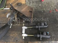
DB36B671-4FAA-4CC2-AE63-1E134A036B5A_zpsqvay8d91.jpg
 
Next project for my '69 is to try to incorporate a Tilton balance bar into the stock(ish) pedal box area. There are balance bar setups that would be bolt in but I dont like that the whole assembly is outside of the firewall.

Time to start cutting
DB36B671-4FAA-4CC2-AE63-1E134A036B5A_zpsqvay8d91.jpg

Very interested in this. I started going the external balance bar route and then shelved it for a while.

What diameters did you pick for the master cylinders?

Also, will you try to incorporate the remote control cable?
 
Last edited:
Very interested in this. I started going the external balance bar route and then shelved it for a while.

What diameters did you pick for the master cylinders?

Also, will you try to incorporate the remote control cable?

They are both 7/8... Total piston area on the front caliper is 11.706 with a 14" rotor. Rear is in the high 6's (changed bore size since this last calculation) with a 13" rotor. Estimated brake torque should be a bit over 3600 foot/lbs. With R compound 335's up front I think it should stop... well. Im using a less aggressive pad than previous with my 1" bore and stock caliper manual brake 5.4:1 ratio... hoping this will be similar feel with less warm up time and less rotor destruction


And yes, Id like to get the remote knob sitting in the dash where the ball vent used to reside.
 
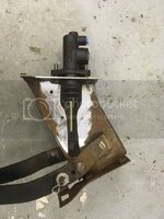
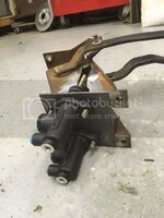
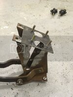
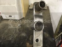
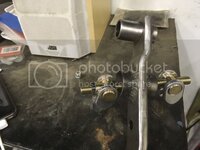
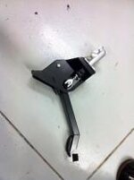
Tacked together... I'll need to open up the channel a bit more. It will also be braced once I confirm everything fits
7C33F23E-42A8-4706-9F66-124A62A0A036_zpsqu2fgp56.jpg

3D6B634D-EDCB-40A1-894A-E7A5F56B868C_zpsm0rioe7a.jpg

2FE2B97B-2A98-45A4-BD24-BCE6FA18B6B1_zpstc9inxvp.jpg
 
Looks great! Thinking outside the box. Keep us updated on the install.
 
Thanks all! I love designing and fabbing these subtle kind of mods... a regular car guy will look and think "huh, a dual master setup" where a corvette guy will look and think "how the hell did he do that?!" :bounce:

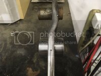
Drilled the arm for the spherical bearing... .25" up to get to 6:1. I also offset it forward in hopes of maintaining some meat on the arm. If anyone has any comments on a loss of strength here please let me know.

445E09B9-3E56-49A0-A9EC-53DCD3B03240_zpshntxqulo.jpg

0A01E68A-B10A-41D8-BE29-8F193DE5F81C_zpsua6v2flc.jpg

6E9C396D-3ACD-4568-A67A-1B1A591B2F41_zpsmsdsfnot.jpg
 
If you have room you could make it an I-beam in that area.

I bet a lot of guys would pay to send you their pedal box for conversion.
 
I love it!
Strength ? I think that you are good on this one , As you are pushing the pedal you will close the gap, if you understand what I mean? And welded all around... No problem for me, I would do the same. In fact I will do the same as I will copy your mod with no shame at all !!!
So! Don't stop and plenty of pictures please. :rose:
 
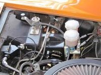
Here are some pictures of local racing Vettes dual m/c that I find too big or too long and too close to the bonnet. Anyway this is why I like your setup.
thum_39345bbdc6b32b7a2.jpgthum_39345bbdc6b347537.jpg
 
If you have room you could make it an I-beam in that area.

I bet a lot of guys would pay to send you their pedal box for conversion.

I love it!
Strength ? I think that you are good on this one , As you are pushing the pedal you will close the gap, if you understand what I mean? And welded all around... No problem for me, I would do the same. In fact I will do the same as I will copy your mod with no shame at all !!!
So! Don't stop and plenty of pictures please. :rose:

Please... copy away!

As far as strength, Im worried about crushing the sleeve... The bearing tolerance is less than .002". If I put 100 lbs of force on the pedal, assuming the masters are hydraulically locked, the pedal should flex (or pivot) about the rear edge of that sleeve (correct me if Im wrong here). If the sleeve is 1" in diameter, half of that is .5. Pedal to the center of the sleeve is 11.25. That gives a ratio of 22.5:1 so at 100 lbs of force on the pedal, there is 2250lbs of force trying to crush this sleeve.
I dont think an I beam would help me here because I already have the center section of the I beam which is what carries this direction of load. I think an H-beam would be more appropriate here, but would require a new pedal design...

Am I overthinking this? Do I need to re-take physics 101? Will real world scenario over-rule theory? :withstupid:
 
Any material you add should help. You could also plate it on either side, using plates with holes drilled for the bearing. If there is room.

For bending beams, I (or as you mentioned, H) are really the best. But they take up space.

Or, You could also static load it and see if the bearing binds.
 
Last edited:
Here are some pics of dual M/C one for a Toy and other two for Porsche 911.

thum_39345bc9681390c48.jpgthum_39345bc96813adb61.jpgthum_39345bc96813a0dcf.jpg

You can see how they used the sleeve. I don't think that you will have any problem with yours. About the pedal pressure you want to apply, just drive a car and try to notice/remember how hard that you need to push to stop or slow down, you will be surprised like I did driving my car at the track.
 
Vette427sbc,

Just a suggestion for possible future fab change to improve strength and keep the footprint small.

To minimize the amount of pedal material removal, you could weld on solid disks to each side of the pedal. Then cut the hole for the spherical bearing. Or Possibly, machine the pedal for bearing and snap rings, then weld disks/tubes onto each side for correct spacing.

I like what you are doing, just adding my 2 cents worth.
 
I guess Im over thinking it... Although if I were to do it again, I like your idea, RTJ. Im going to see if I can come up with a way to incorporate that idea into my current setup.

As far as the pedal forces, I think 80lbs at the pedal is the "norm" for a manual brake setup. 100 lbs is what was calculated as my maximum input during braking force calcs, so Im building this around that number + some safety margin. Most racecars are torn down and thoroughly inspected after x amount of hours. Im (trying to!) build and design this car as if a big manufacturer engineered it to be a daily driven car that you shouldnt have to schedule critical system inspections. I plan to do that anyway prior and post track/hard driving events, but Id rather keep that thought in the back of my head when Im out picking up groceries or running errands in this thing :D
 
I found this kit for C3. Good for info and ...cost!

https://www.compbrake.com/product/c...pedal-box-kit-hydraulic-dual-ap-cylinder-kit/

And I think that is the one in the orange Vette picture posted in few posts earlier.

I saw that one as well... It looks like the nicest one out there, although still outside of the firewall and more unnecessary weight! Im interested to see how or what they are doing with that new 5:1 pivot arm... but too little leverage for me anyway
 
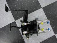
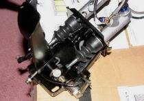
Final mock-up in the car:
thum_6155c203904747db.jpg

thum_6155c203904800d6.jpg

thum_6155c20390468619.jpg

I'll have to get a coupler to extend the pushrod to get more thread engagement, but otherwise I'm happy with fitment and clearances. Paint and final assembly in the car next!
 
I see you closed the gap in the clutch rod hole. Are you using a hydraulic system? Do you think that plate is stiff enough?
 
Top