Is there a way to quantify frame stiffness?

clutchdust

Millionaire Playboy
Joined
Mar 27, 2008
Messages
1,728
Location
In transition
I'm talking about a real person's way, as in, in their own garage. I know engineering shops can test various combinations and get a frequency value, but for those of us that just have a MIG welder in our garage is there a way we can figure that out too? I would be happy with a reasonable approximation. But we all know that if we put a roll cage in our car, it makes the structure stiffer, which is a good thing on multiple fronts, but can you quantify it?
I don't necessarily have to say it's 'x' frequency. But when I do modifications, I would like to be able to say this change increased the torsional stiffness 'x'%, etc.
 
A long beam sideways bolted to the front or rear suspension. Rest of the frame (if looking at the front secure the rear and vice versa) either weighted down on stands or secured to a jig so it doesn't move. Then put a known weight on the end of the beam to torsionally load the frame. Check the deflection of the front. Do your stiffening and check again.
 
OK, I think I can picture what you're saying. Question is, what do I do with that information? For instance, let's say I do what you're describing and I get a 5/16" of flex (Just pulling a number out of my ass for the sake of the example). I then make the changes I'm considering and that goes to 2/16". Is that a straight algebraic equation to quantify?
 
Measuring the actual deflection of a fully assembled car would be the way i'd do it.

Get a couple of those cheap laser levels and temp attach them to the front and/or rear of the car. Drive one wheel of the car up on a ramp while taking measurements with respect to how much deflection is seen with repect to the opposite end of the body of the car.

Get out your statics book to find the proper formulae to figure the stiffness of your beam ( the car will model as an equivalent single beam ). Knowing the distance between the laser level and the point where the deflection is measured, the deflection and the force applied (you'd need a scale under the ramp) allows us to calculate an equivalent beam. That gives the effective lengh of the beam, beam deflection and force applied to cause that deflection. The applied force would be the normal weight of that wheel when the car is sitting level minus the acual reading when the wheel is on the ramp. I or several of the other very sharp engineers here can help you with the calcs.

Make changes to the car to add stiffness. Repeat the same measurements.
 
Last edited:
Wow, a couple really good ideas here, and cheap! I like it.
I do like the idea of the lasers as they are really cheap and won't require any significant modification to the car to attach. Now it's just time to feed the hamster and get some ideas cooking.
 
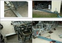
Like 69427 showed in his pickie.
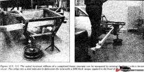
These images show a full scale done in Australia.

thum_12694f06e4d8c2aec.jpg

Note: one end welded and bolted to the floor. Also note all links/shocks replaced with rigid bar.


Sample values in ft/lbs/deg.

Lotus Elise :8000
Porsche 911 :10,000
Mclearn F1 :25,000
Mazda Miata :3800
Porsche 906 :1700
Porsche 904 :1500
Mclearn M6B :6000

Cheers - Jim

I'll add: See Pages 96&97 in Herb Adams' Chassis Engineering. I'll scan after work.
 
Last edited:
Guys,

Keep in mind that there are two basic numbers here (That I am aware of). One is beam stiffness and the other is torsion stiffness.

Beam stiffness is what the middle of your car does when you sit I it.

Torsion stiffness is what happens when you jack up only one corner.

Stiffness is proportional to a point. That is getting half the movement is because you now have twice the stiffness. However once you go under that point, you will have gone too far and will need a new frame.

George
 
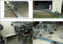
Like 69427 showed in his pickie.
These images show a full scale done in Australia.

thum_12694f06e4d8c2aec.jpg

Note: one end welded and bolted to the floor. Also note all links/shocks replaced with rigid bar.


Sample values in ft/lbs/deg.

Lotus Elise :8000
Porsche 911 :10,000
Mclearn F1 :25,000
Mazda Miata :3800
Porsche 906 :1700
Porsche 904 :1500
Mclearn M6B :6000

Cheers - Jim

I'll add: See Pages 96&97 in Herb Adams' Chassis Engineering. I'll scan after work.

WTH is a pickie?
 
It was early and I am a shittytypist - pic-ie aka "image" :photo: - not to be confuse with a pickle - something that might not have been so forgiving!
Cheers - Jim
 
Aww - Couldn't say -- justa term I picked up overseas - pic-ie, snaps, etc . Have just used since

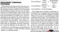
But as promiced - belatedly - here is a quick scan from Herb Adams' Chassis Engineering (as a preview). Sorry for the image, the scanner settings were off - but you 'll get the picture!


thum_12694f0875606e35b.jpg

thum_12694f08757f7af9c.jpg

Most of the last para - is writing to the chassis they were building in th etext - but note they were satisified with 10 Kftlbs per degree as VERY GOOD. They weren't so scientific as to include the bend in the timber - but they must have assumed negligible.

Cheers - Jim
 
Mike, what kind of number did you come up with when you did this?

I'm still looking for the notebook I wrote stuff in while I was doing this. (I've moved twice since then, and am still trying to get organized.) I do recall the frustration of having to confine the changes primarily to the frame rails as there's just not enough room in the trans tunnel to add a proper torsion tube/box to get some significant improvement in the frame's rigidity. I didn't think to measure the stock frame before I cut it up a bunch, so I don't have a good A-B comparison. IIRC, I ended up somewhere in the low to mid 2000 lb-ft/deg.
I think I added about 30 pounds of additional material on and in the frame in the process. I had several other ideas of where to place additional structure, but it got down to an educated guess of whether I'd lose more cornering speed from the additional weight than I'd gain from the additional structure stiffness.
In the back of my mind I keep hoping I'll run into a decent deal on a C3 body (no frame) and then cut the dickens out of the tunnel to put in a torsion box, along with cutting out the rear storage boxes to put in the C5 rear suspension that I really wanted when I put the C4 suspension in the current frame, and also perhaps widen the rear fenders about an inch and a half each to stuff some wider rubber in there without noticeably changing the body appearance. (I actually don't need another project, so perhaps it's just as well that I haven't run into a cheap price on a spare body.:amused:)
 
Did you do any node measurements that might show whether there is more twist in the front of the frame or the rear?
 
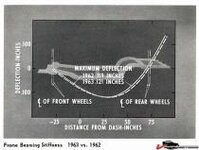
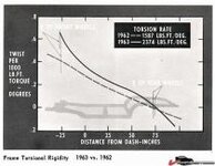
From the 1963 SAE paper the Corvette Stingray, I think you want the graphs from pages 16 and 17. It shows the beam stiffness and torsional stiffness of the C3 frame.

page 16.
Beam Stiffness: with 1500 pound at drivers seat, frame deflects .121 inches midspan with the front and rear frame held at zero.

page 17
Torsion Stiffness: 2374 ft-lbf/deg

I think I downloaded the paper from this forum....
 
Mike, what kind of number did you come up with when you did this?

I'm still looking for the notebook I wrote stuff in while I was doing this. (I've moved twice since then, and am still trying to get organized.) I do recall the frustration of having to confine the changes primarily to the frame rails as there's just not enough room in the trans tunnel to add a proper torsion tube/box to get some significant improvement in the frame's rigidity. I didn't think to measure the stock frame before I cut it up a bunch, so I don't have a good A-B comparison. IIRC, I ended up somewhere in the low to mid 2000 lb-ft/deg.
I think I added about 30 pounds of additional material on and in the frame in the process. I had several other ideas of where to place additional structure, but it got down to an educated guess of whether I'd lose more cornering speed from the additional weight than I'd gain from the additional structure stiffness.
In the back of my mind I keep hoping I'll run into a decent deal on a C3 body (no frame) and then cut the dickens out of the tunnel to put in a torsion box, along with cutting out the rear storage boxes to put in the C5 rear suspension that I really wanted when I put the C4 suspension in the current frame, and also perhaps widen the rear fenders about an inch and a half each to stuff some wider rubber in there without noticeably changing the body appearance. (I actually don't need another project, so perhaps it's just as well that I haven't run into a cheap price on a spare body.:amused:)
This is the plan. There's plenty of room to take the trans tunnel up and run some fore-aft bracing in there. Planning on a 'Y' to distribute load to the rear framerails around the diff mount in the back and strutting off the Lakewood bellhousing in the front. From there kind of spidering out as best I can to hit the front framerails. I'm really tempted to load the block but find that a bit of a scary proposition.
 
From the 1963 SAE paper the Corvette Stingray, I think you want the graphs from pages 16 and 17. It shows the beam stiffness and torsional stiffness of the C3 frame.

page 16.
Beam Stiffness: with 1500 pound at drivers seat, frame deflects .121 inches midspan with the front and rear frame held at zero.

page 17
Torsion Stiffness: 2374 ft-lbf/deg

I think I downloaded the paper from this forum....

Do you have the download? Sound interesting.
 
Top