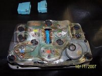
Instrument cluster ???

BangkokDean

Well-known member
Joined
Mar 25, 2008
Messages
3,343
Location
Bangkok
I had removed the instrument cluster on the 81 and cleaned and repainted the insides white and added LED lights. Now my amp gauge is pegged full charge when switch is on, plus the water temp gauge does not work. As for the oil pressure and fuel gauge they are fine, the oil temp not sure as I have not left it running long enough.

I did read the other posts on water temp gauge and the gauge pegs when grounded plus I installed a new sending unit.But still no go. Now I am wondering if I have put the gauge unit back together correctly? BTW I also replaced the printed wiring board. Does any one have a diagram of how to put all the resistors and spacers back together, in pictures or diagrams?
:sos::sos:
 
amp gauge? you shouldn't even have an amp gauge in 81

Resistors and spacers? There's only the printed circuit and the little lights and a couple of nuts for the gauges. Are you sure the little "flaps" that make contact with the connector are properly seated and not touching?
 
Sorry meant Voltmeter gauge. So I should remove the things that jump the posts that have different colors in the center?

100_2678.jpg


also is there a fuse that powers the gauges?
 
Last edited:
I'm not following, what things jump posts?

All you should have is the back of your console and a printed ciruit held on w/ the bulbs and some nuts to gauges.

This

81-82center5.jpg
 
BTW, that appears to be an 82 one. the circuit flap on the bottom right is folded away on thos. That was originally power & gnd for the clock, 82s have an oil temp gauge there so that's not used, a separate connector goes to the oil temp gauge.
 
BTW, that appears to be an 82 one. the circuit flap on the bottom right is folded away on thos. That was originally power & gnd for the clock, 82s have an oil temp gauge there so that's not used, a separate connector goes to the oil temp gauge.

I know, I took that picture from another thread the flap I taped over like the original was. So my question is is there a diagram showing where the resistors go and what spacers go where. The resistors have different colors on them plus I have two extra washers left over and they look to be some kind of insulating material.

Also is there a fuse for the gauges?
 
The one in your pic is molten and all done. You need a new printed circuit.

I was referring to the flap in my pic, yours is hooked up to the stock clock.

There is a gauges fuse but looking at your printed circuit that's the culprit right there.
 
The one in your pic is molten and all done. You need a new printed circuit.

I was referring to the flap in my pic, yours is hooked up to the stock clock.

There is a gauges fuse but looking at your printed circuit that's the culprit right there.

Again that is not my picture, my printed circuit is new. What fuse takes care of the gauges?
 
I'm not following, what things jump posts?

All you should have is the back of your console and a printed ciruit held on w/ the bulbs and some nuts to gauges.

This

81-82center5.jpg

That looks like mine there. In that picture there is a resistor that is white with assorted colors in the center. The extra insulating washers (2) maybe someone else will know where they go.

Thanks
 
Oddly enough, it's the "GAUGES" fuse.

ANd there I go thinking again- most of the resistors across the gauges I recall seeing are on top of the printed circuit.
 
Oddly enough, it's the "GAUGES" fuse.

ANd there I go thinking again- most of the resistors across the gauges I recall seeing are on top of the printed circuit.

The resistors go under the printed circuit. I also advise using the original little speed nuts on the printed circuit and not replacing them with new hardware, it seems that new hardware has a different resistance and can affect the accuracy of the gauge.
 
Top