Camber and placement of strut rods for 6-link

BBShark

Garage Monkey
Staff member
Joined
Mar 5, 2008
Messages
4,864
Location
Right here
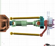
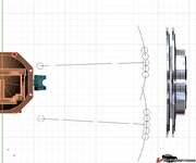
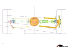
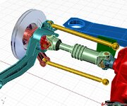
I am placing the inner mounts of the upper and lower links on my suspension. I have placed them so that I get .5 degree camber gain for every 1 inch of compression (at the struts). The circles in the line drawing (last picture) are 1 inch diameter. The rebound camber changes .4 degrees in the first inch and .1 in the next. So there is .5 degrees total in 2 inches of rebound.

Like to get some opinions before I make the brackets.

This is for a street driven car that might see some Auto-X but no track time.
44b75543b82ff8.jpg

44b75543c9415d.jpg

44b75543d45f77.jpg
 
This thing can't be defined without other parameters!

First of all you must fix the max roll angle that the car will have at nearly 1G of lateral acceleration (roughly the limit you will have with a well designed 6-links).
Then you must know which kind of tires you will have at the rearend..... lower tire wall will need less camber gain, thanks to the lower deflection under load.

Remember that moving the pivot of the braket will change even the swing-arm lenght and the position of the roll center of the rear-end.

My opinion is to try to keep the higher bracket as flat as possible at ride height...... and to change the camber gain moving the inner lower pivot.

Just my 2 cents....
 
Last edited:
BBShark -
Nice models - are they in the downloads section? WHich modeling program? Rhino maybe? COuld use some of those files too if they're available.

Thanks - Jim
 
This thing can't be defined without other parameters!

First of all you must fix the max roll angle that the car will have at nearly 1G of lateral acceleration (roughly the limit you will have with a well designed 6-links).
Then you must know which kind of tires you will have at the rearend..... lower tire wall will need less camber gain, thanks to the lower deflection under load.

Remember that moving the pivot of the braket will change even the swing-arm lenght and the position of the roll center of the rear-end.

My opinion is to try to keep the higher bracket as flat as possible at ride height...... and to change the camber gain moving the inner lower pivot.

Just my 2 cents....


OK, Just took another look at this after modeling a C5 rear for camber gain and roll center. This is as close as I can probably get since I can not move the outer points.

Previous placement on left and new on right.

44b7a14b2359e3.jpg
 
The shorter upper bracket will give more camber gain.

If you are planning to use low profile tires, I will suggest a negative camber of no more than 1-1.5°

Like I sed before, if you plan to use stiff springs and an effective sway bar, you can calculate some 2° of roll angle in a fast corner.

A low profile tire (like the ones used in a C6, for example) will have a very little deflection under side load, so your camber gain must only compensate for the body roll angle.

Of course with such stif rearend you need a stiff frontend, otherwise you will have a lot of oversteer.Basically you must take in consideration the whole suspension system, front and rear. They have to work together.....

The rule is that it is impossible to have "the perfect suspension"...... only the best compromise will be our target!

You allready have the front setup defined?
 
I'm about to tackle the 6-link for my '70. I'm going to weld the inner link of the upper strut to the dif crossmember (ala Norval!). I believe Norval used a 13.5" upper control arm and the stock-length lower. He set his up for nearly 0 camber gain. The Giovanni setup in the Corvettefaqs looks very similar. I wonder if you can model a 6-link that toes out during rebound and toes in during jounce? It would possibly necessitate yoke movement in and out to effectively lengthen and shorten the struts to affect the toe, probably no more than .25". I'm no engineer so I don't have access to CAD programs. I just welded in my Johnny Joints in place of the control arm bushings today and I would appreciate any details concerning these 6-links.
I'm also raising my differential about 1.5" so I can start with the Power Manual geometry, I believe it recommends the inner halfshaft should be 1" above the outer shaft.
 
Started on the 6 link

Here goes!
Cut the axles at the C-clip:
VetteProject084.jpg

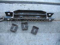
Modded the stock lower strut bracket:
VetteProject086.jpg

Mocked up the rods, upper is 13.5" long and lower is 16.7". The upper rod will be virtually parallel to the half shaft:
VetteProject088.jpg

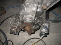
Made a mounting bracket that fastens to the diff. 1/4" steel plate:
VetteProject090.jpg

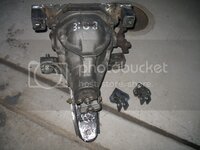
Another view of diff with upper and lower strut mounts and the upper/outer mounts tacked together:
VetteProject092.jpg

I should have some more pics of all this bolted in the car within a week or so.
 
I use a drag vette 6 link with stock length axles ... My inner yokes are not clipped either .. Something you might want to check is if the inner yokes get pushed to far into the diff. My upper and lower links are the exact same length as the half shaft, so my yokes don't move in and out. The stock axles length is 13 7/8 - 13 15/16. If your upper rod is only 13 1/2, i think it will be moving the yoke around in the differental a little to much. I know norval uses a splined half shaft, with fixed inner yokes, to avoid this problem. Maybe you will be OK, i would like to know just how much your yoke does move with your setup. I would think that your minimum length of your strut rods would have to be the length of the half shafts (13 7/8 - 13 15/16). Anyway good luck and looks good.

I am correcting my first statement ... I think!!! that norval uses splined half shafts .... thought i had pictures of his set up but i can't find them. But i would still like to know how much your inner yokes move. I see alot of other people don't use splined shafts so maybe the yoke movement is not an issue.
 
Last edited:
I measured the half shafts and they looked to be 13.5" long. Maybe I missed the mark a little but I can always lengthen the rods.
I copied one of Flexusmark's designs. He had a CAD setup using 13.5" upper rods, virtually parallel to the half shafts. That setup moved the yoke about .12" through 4" of verticle travel at the spindle, starting with the half shafts angled down toward the spindles with a 1" drop - moving the spindle from -3" below parallel to +1" above parallel. I don't think I'll have any issues with the axles collapsing into the cross shaft but I'll take a good look when I pull the cover off.
 
I doubt you will have any issues with the axles hitting the differential pin .. because you cut the end off at the snap ring ... but i would be a little concerened about how far the yoke went into the seal ... if you are only getting .120 movement i would think you are pretty safe with that. Can you change dimensions in that cad model? .... i would be courious to see what kind of movement you get with a 14" upper rod.
 
I don't actually have a CAD program. Flexus just posted pics of his CAD drawing on the CF forum many years ago and I used them to build my setup. He used to offer the files to anyone who was interested but I haven't seen him around on the Forum for awhile.
 
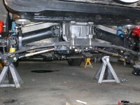
First mock up of 6 link

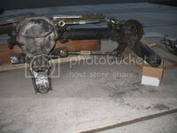
Diff mounted with struts attached:
VetteProject103.jpg

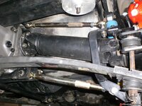
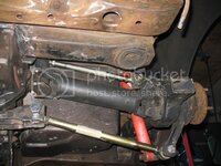
View of upper strut:
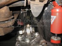
VetteProject104.jpg

A closeup of upper strut, I still have to finish-weld the outer strut mount:
VetteProject105.jpg

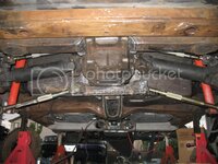
A look at both sides, neither set at ride height:
VetteProject106.jpg

I think I'll mod the frame rails at the bump stops to get a little more room for upward travel, maybe an inch to 1.5". I may wimp out though and just mount the stops flush with the frame, eliminating the metal bracket it's normally attached to. That would give me about 1/2".
 
A couple more updates

I did some more fab this weekend.
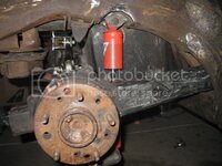
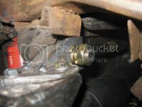
Old bump stops just don't align well with new 6-link mount - too low and too far forward. With the raised diff and shock mounts, I was only getting about 3" of travel on the Konis (4" is available):
VetteProject110.jpg

I moved it back a little bit to center it between my upper strut mounting tangs, and outboard about 1 inch to clear the rod end. It shouldn't interfere with my 17x11 ZR-1 wheels(3" adapters required), as I mocked-them up to check clearance:
VetteProject114.jpg

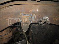
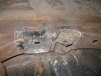
Another view from the bottom. I actually cut the bottom of the frame and bent the tab up into the frame about .5". The upper strut mount now has more room to move up into the pocket I created:
VetteProject113.jpg

I also added a 1" x 3" x .125" steel box to the top of my modified diff crossmember:
VetteProject117.jpg

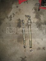
Then I finished the 103 degree weekend yesterday by welding bored-out nuts to my AFCO upper and lower strut rods so it will be easier to get the jam nuts tight:
VetteProject118.jpg

After notching the frame and moving the bump stops up I had to notch the rear cargo compartment to clear the outer half of the upper strut rods at full jounce. Don't have any pics of that yet though.
 
Top