Ackerman angles

bahamasair

Well-known member
Joined
May 11, 2008
Messages
112
Location
Bahamas
I'm trying to get the best angles possible for the tie rods on my rack install but have a couple of questions. Looking at this pic
bumpsteer.jpg

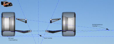
you need to get the instant center to line up any of the other measurements but if I extend the lines along my a arms they will never meet
ackermanlines.jpg

(thats not my car but is the same setup.)
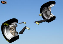
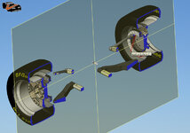
Looking at the first pic it shows instant center being behind the a arms but like my 2nd pic shows that will never happen. Should I be measuring from where the ball joints mount to the steering knuckle spindle like this?
ackermanlinesfromsteeringknuckle.jpg
Even if I do it wont make the instant center intersect behind the a arm. Should I assume instant center to be in front of the a arms like this?
ackermanlinesinfrontofaarm.jpg

Id like to get this as close as possible and since the body is off it will be easiest to measure it now.
I'm thinking I can get the instant center by extending my lines toward the wheel side of the a arms but would like to be sure and also want to be sure on where to measure at the steering knuckle.
Thanks for any help.
 
Last edited:
The center of the balljoint is your pivot, and your pic shows perfectly the main problem on the front of these cars, an IC outside of the car, and as a result a wacky camber gain in the wrong direction. Even those van steel arms do nothing to fix it. I addressed this many years ago on CF. Although those pics make it seem a lot worse than it is because of the ride height (for susp. travel the shorter upper arm angles a lot more than the lower one), even at static ride height without the car slammed the IC is outside of the car. The proper solution is an extended spindle, an extended ball joint or a lower cross shaft mounting location.

Ackerman angle is from a birdseye view the angle that the steering arm makes with the steering axis at that level, it should intersect with the center of the rear axle so that this is the turning point. Ackerman makes for a difference in toe output for the inner and outer wheel because they scribe different turning radii in a corner.

Read the tech articles, I wrote a couple about this stuff, the explanation for ackerman is in there too.
 
The center of the balljoint is your pivot, and your pic shows perfectly the main problem on the front of these cars, an IC outside of the car, and as a result a wacky camber gain in the wrong direction. Even those van steel arms do nothing to fix it. I addressed this many years ago on CF. Although those pics make it seem a lot worse than it is because of the ride height (for susp. travel the shorter upper arm angles a lot more than the lower one), even at static ride height without the car slammed the IC is outside of the car. The proper solution is an extended spindle, an extended ball joint or a lower cross shaft mounting location.

Ackerman angle is from a birdseye view the angle that the steering arm makes with the steering axis at that level, it should intersect with the center of the rear axle so that this is the turning point. Ackerman makes for a difference in toe output for the inner and outer wheel because they scribe different turning radii in a corner.


Read the tech articles, I wrote a couple about this stuff, the explanation for ackerman is in there too.


I realize that happens, the thing I dunno is WHY?? the same deflection on both wheels has to happen when the tie rods are moved...why should one wheel turn more than the other?? as I recall some Ackerman was desirable...
Didn't Norval extend his spindle height?? almost 2" worth??

:amazed:
 
Think about it, when you go around a corner the inner wheel makes a shorter tuning circle than the outer wheel, as such the inner needs more toe angle than the outer one. At higher speed you make small steering inputs so not very noticeable there, when doing large inputs like parking or a slow hard corner you will notice it.

image002.jpg


Yes, Norval extended his spindle. don't know if it was 2", sounds like a lot. Ideal is right around .7" from what I figured out myself. I have an extended balljoint instead.
 
You can get the extended Ball Joints with the SPC Upper A Arm from Mark Savstke. :amused:
His price was better than direct from SPC - Formerly sold by Pitstop I recall.
Hope it al makes a Big difference when I get the Beast rolling again.

Cheers - Jim
 
I have those, from back when they were still pole position racing products arms (and not bolt on). They are drilled for the mini ball joint pattern and you can get extended ones for those from most speedshops.

24819ba2b7c0d3.jpg
 
I've got those a-arms with the extended ball joint, and they do give you a better camber curve.

8648296a5404fa2.jpg

camber.jpg
 
The center of the balljoint is your pivot, and your pic shows perfectly the main problem on the front of these cars, an IC outside of the car, and as a result a wacky camber gain in the wrong direction. Even those van steel arms do nothing to fix it. I addressed this many years ago on CF. Although those pics make it seem a lot worse than it is because of the ride height (for susp. travel the shorter upper arm angles a lot more than the lower one), even at static ride height without the car slammed the IC is outside of the car. The proper solution is an extended spindle, an extended ball joint or a lower cross shaft mounting location.

Ackerman angle is from a birdseye view the angle that the steering arm makes with the steering axis at that level, it should intersect with the center of the rear axle so that this is the turning point. Ackerman makes for a difference in toe output for the inner and outer wheel because they scribe different turning radii in a corner.

Read the tech articles, I wrote a couple about this stuff, the explanation for ackerman is in there too.


I realized I screwed up with the Ackerman title after I posted but couldn't change it.
So from what you are saying if I get the car at about ride height the angle wont be as bad and a .7" extended ball joint will move the instant center to the rear of the arm? I'm a little worried about how my Van Steel arms with coilovers are going to work. It is under a shitload of pressure and is at the highest the a arm can travel. I have the springs at the lowest setting and if me and one of my friends stand on the front of the chassis and bounce up and down the coilovers never move ( between us we weigh about 500lbs). I have the big block and gearbox on the chassis and about the only thing that is missing is the body. I don't see the weight of the body compressing the springs enough to lower the car to any kind of reasonable ride height but I guess I will find out sooner or later.
 
I've got those a-arms with the extended ball joint, and they do give you a better camber curve.

8648296a5404fa2.jpg

camber.jpg

Will those BJs fit a stock arm, and how much longer is the stem, and do you have a part #??

:bump:

no they will not fit a std. arm. Mine didn't even fit my spindle, I had to ream them out to get the castle nut on far enough
 
I realized I screwed up with the Ackerman title after I posted but couldn't change it.
So from what you are saying if I get the car at about ride height the angle wont be as bad and a .7" extended ball joint will move the instant center to the rear of the arm? I'm a little worried about how my Van Steel arms with coilovers are going to work. It is under a shitload of pressure and is at the highest the a arm can travel. I have the springs at the lowest setting and if me and one of my friends stand on the front of the chassis and bounce up and down the coilovers never move ( between us we weigh about 500lbs). I have the big block and gearbox on the chassis and about the only thing that is missing is the body. I don't see the weight of the body compressing the springs enough to lower the car to any kind of reasonable ride height but I guess I will find out sooner or later.

Rear of the arm? The lines you drew and the figure above it are for the instantaneous center in relation to roll center height and camber curve and steering angle result of tie rod geometry (bump steer) It all takes place in the frontal view plane and more precisely it's in a plane through the steering axis (keep in mind kingpin inclination) So from the frontal view those lines should intersect on the inside of the suspension corner not the outside. Behind the wheel has nothing to do with it.

Like this:
rollcenterfr.jpg

Works in this plane:
casterplane2.jpg

casterplane3.jpg

As for the van steel stuff, wouldn't be surprised if their coil overs are too long, most others are. The Semi coil over junk from speed direct is (shark byte?) I think the Jim Meyer stuff is about correct with the way they use a u clamp to mount off the stock hole for the pedestal mount. Van Steels are the same I think so it's all in the shock length. You'd need about the shortest shock available or a set of lower arms with a dropped lower shock mount.

Can you take a frontal pic of your chassis as it sits now se we can see how the arms angle?
 
no they will not fit a std. arm. Mine didn't even fit my spindle, I had to ream them out to get the castle nut on far enough

Thats odd, the castle nut went on too far on my car. I had to install a washer under the castle nut to engage the cotter pin correctly.

TT is correct, these ball joints don't work on a stock a-arm. However, you might be able to piece together an extended version using a Howe corvette ball joint and replacing the stude with a longer one. I just purchased mine as a unit with the control arms.


http://www.howeracing.com/t-SuspensionBallJointHousingsTable.aspx

http://www.howeracing.com/t-SuspensionUpperReplaceStudsTable.aspx
 
OK, to raise the pivot point of the upper ball joint with a longer stem or modded up spindle, that would make the front end bite better in a corner with modern tires, I suppose....

but conversly wouldn't that make the rear want to swing around making the car more tail assed light?? just by the feel of it...

:hunter:
 
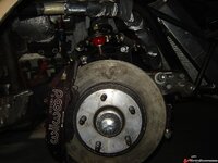
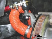
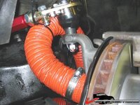
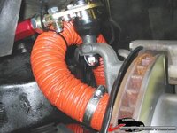
Something is wrong with my camera and someone stuck a gun in my wifes face and took hers so this is the best I can do right now. Its leaning to the right because the tire is flat.
I took some pics in the day and they came out much better so I replaced the originals. It doesnt look like its leaning right any more but does look like its leaning left so it must be the ass behind the camera and not the low tires.
DSC02806.jpg

DSC02804.jpg

DSC02805.jpg

DSC02807.jpg

DSC02812.jpg
 
Last edited:
I think Im just going to make the tie rods as long as I can and call it done. It should be good enough for what I'm going to do with the car and I keep over thinking everything making this project take too long. Ill let you guys know if I run into a wall because of bump steer if I ever get the car back together.
Thanks for all the good info. I at least now know more about steering than I did before :)
 
Top