agent20x
Well-known member
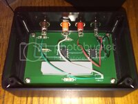
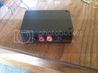
Ok so I finally finished it and it works. It didn't actually take that long, I just never had much time to dedicate to it.
I guess we need a brief history of what I was trying to do. I ordered the autometer quad gauges and the gauges are only set up for a fuel sending unit that they provide ( which won't fit without a decent amount of tinkering and gas tank removal) which operates in the 33(full)-240(empty) ohm range. Needless to say this will not work with our stock sending units which operate in the 0(empty)-90(full) range. So, using a fairly simple opamp circuit I was able to make it work with the existing fuel sending unit. The result is a box that you can plug inline with the sender and new gauges that corrects the voltage readings for the new gauge.


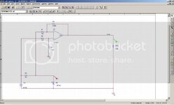
Here is a schematic of the circuit in question.

The little sub-circuit in the bottom left is the pre-existing gauge circuit that you tap off of.
First off, this was not very cost effective for me, however if there is anyone else out there trying the same thing it will cost you less than it cost me. The final design cost about 70 in parts(including the printed circuit board). You could do it for a little less if you built your own circuit board or use one of those universal kits at radioshack. However, I opted to save myself some headaches and have the board built for me by an outside company for about 33 (if you order at least 5 you can get that price down to 25 each).
If anyone finds themselves in a similar situation I can post part numbers and links. Anyone that can do a decent soldering job could do this themselves. :beer:
I guess we need a brief history of what I was trying to do. I ordered the autometer quad gauges and the gauges are only set up for a fuel sending unit that they provide ( which won't fit without a decent amount of tinkering and gas tank removal) which operates in the 33(full)-240(empty) ohm range. Needless to say this will not work with our stock sending units which operate in the 0(empty)-90(full) range. So, using a fairly simple opamp circuit I was able to make it work with the existing fuel sending unit. The result is a box that you can plug inline with the sender and new gauges that corrects the voltage readings for the new gauge.


Here is a schematic of the circuit in question.

The little sub-circuit in the bottom left is the pre-existing gauge circuit that you tap off of.
First off, this was not very cost effective for me, however if there is anyone else out there trying the same thing it will cost you less than it cost me. The final design cost about 70 in parts(including the printed circuit board). You could do it for a little less if you built your own circuit board or use one of those universal kits at radioshack. However, I opted to save myself some headaches and have the board built for me by an outside company for about 33 (if you order at least 5 you can get that price down to 25 each).
If anyone finds themselves in a similar situation I can post part numbers and links. Anyone that can do a decent soldering job could do this themselves. :beer:
