Sender unit hell

saudivette

Clueless In Sandland
Joined
Mar 24, 2008
Messages
2,633
Location
Aussie expat in Saudi Arabia
I went to remove my old tank sender unit today so that I could fit the new one preparitory to modding the rear deck to take the Monza style cap.

It went downhill from there :suicide:

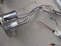
Once I got the old unit out of the tank, I placed it and the new one side by side and it didn't take a whole lot of time to realise that they're wired differently:
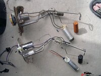
354a0c352758fd6.jpg

On the old one, the two (black) wires are bolted to the motor whereas on the new motor, there's a plug with one black and one red wire coming from it and the unit has one black and one grey wire to attach to the motor. What colour goes to what on the new one? Also on the old one, one of the black wires runs though what looks like a capacitor :confused: What's that all about?
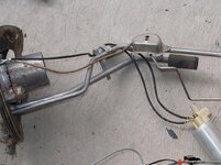
354a0c352940909.jpg
354a0c352871646.jpg

I did plug the new sender unit into the car harness and tried touching the motor wires to the black and grey wires but couldn't get the motor to do squat. I ran a multimeter in the plug and am getting around 8 volts when I bridge two of them but nothing at all with the third wire in the plug (can't remember which colours). I'm not real concerned about that for now as it could be a relay or fuse or something and I did touch the motor to the battery and it spun, so I know it works but I need to know what way to wire up the motor so I can get the sender unit mounted in the tank.

That was not the worst of it. Did I mention that the old sender unit had been leaking a little bit at the 6 o'clock position? Did I mention that that bolt wasn't present when I went to take the sender unit out? Sorry, that's incorrect, the bolt was present but the bolt head was not! Some arse piece has snapped a damn bolt off in the hole!!! I managed to get a hole drilled down into the bolt and started an easyout going. I think the stud actually moved a little before the easyout snapped off! I've spent the whole day trying to get the stud/easyout combo out of the hole. Probably a little bit of an understatement to say I'm pissed off!!

Anyway, and ideas on the motor wiring would be appreciated. Thanks guys :thumbs:
 
Last edited:
Keep in mind the +12 to the motor is operated via the fule pump relay which is on for just a second to pressure the system, then to start the car it obvously stays running, if the engine dies for any reason, the pump dies also about a second later.....in case of a wreck, like.....

so from the visual it looks like that gray wire on the new unit is the + or red on the pump, black is ground at any rate....

that sender looks like the purple wire....the old sender looked brown....

so that leaves the gray wire needs go to the fuel pump relay....

I think I made sense....

:stirpot::lol:
 
The polarity of your new pump is embossed into the plastic, so there's no guessing there.

is that a TBI or TPI pump (I hope for you you went with the TPI one)

The gray wire should be + and should go to the wire on the OEM one that had the capacitor. Looks like that's the gray wire on your new sender also. Just check it against the original connector, tan/white should be 12V to the pump. I know scotch connectors are a bad idea...

4uf57k.jpg

2epre41.jpg


Didn't you get one of those rubber isolator socks with your pump? They greatly reduce the noise coming from the pump.

If you have a TPI pump, secure the rubber hose between steel line and pump with either hose clamps or those little hose clamp spring thingies. Last thing you want is your hose to come off.
 
The polarity of your new pump is embossed into the plastic, so there's no guessing there.

is that a TBI or TPI pump (I hope for you you went with the TPI one)

The gray wire should be + and should go to the wire on the OEM one that had the capacitor. Looks like that's the gray wire on your new sender also. Just check it against the original connector, tan/white should be 12V to the pump. I know scotch connectors are a bad idea...

4uf57k.jpg

2epre41.jpg


Didn't you get one of those rubber isolator socks with your pump? They greatly reduce the noise coming from the pump.

If you have a TPI pump, secure the rubber hose between steel line and pump with either hose clamps or those little hose clamp spring thingies. Last thing you want is your hose to come out.


Yeh I hate that too....:devil:
 
The polarity of your new pump is embossed into the plastic, so there's no guessing there.

is that a TBI or TPI pump (I hope for you you went with the TPI one)

The gray wire should be + and should go to the wire on the OEM one that had the capacitor. Looks like that's the gray wire on your new sender also. Just check it against the original connector, tan/white should be 12V to the pump. I know scotch connectors are a bad idea...

4uf57k.jpg

2epre41.jpg
Sorry to sound dull and shit but I really, really, REALLY hate electrickery and pretty seriously struggle to undertand it. TT, where's the damn polarity embossed?? TBI huh? TPI huh? Please guys, when it comes to elecktrickery, I am a retard - you have my full permission and blessing to speak to me on all matters electrical, as if I am mentally challenged! Seriously.

Didn't you get one of those rubber isolator socks with your pump? They greatly reduce the noise coming from the pump.

If you have a TPI pump, secure the rubber hose between steel line and pump with either hose clamps or those little hose clamp spring thingies. Last thing you want is your hose to come off.
I got a piece of rubbery stuff, looks like something you'd see on the handle of a fishing rod and is about the right size to slip over the pump - I guess that's where it goes.

The rubber hose that connects the pump to the steel line is what I would call a "teaser" - it's almost long enough to connect the two parts to each other! If I connect it to both, then each end will be held there by about 3mm. Can't I use a piece of regular 5/16 fuel hose to join them or doesn't that type of hose like to be fully submersed in fuel?
 
Last edited:
TPI = tuned port injection pump, capable of higher dead head pressure (more flow) than the TBI (throttle body injection) pump. Pump does not create pressure, it creates flow. Regulator (restriction) creates (regulates) pressure. Simply put, you can put a TPI or even LT1 pump in there and it will not struggle to achieve 12lbs system pressure like a TBI pump will do over time.

Check the white part on the pump, one of the 2 sides should have either a + or a - embossed on them. if not, I'm pretty sure the gray wire is 12V+

The pic has the rubber boot around the pump, check it out.

Replace shitty hose w/ reg. Fuel injection hose.

in the diagram, 120 = fuel pump (on the left side) M stands for Motor.
 
Righto, thanks for the info guys. I haven't had a chance to get back onto it yet but I'll go and have a look today. From what you are saying TT, I assume I have a TPI pump. Also, what's the difference between fuel injection hose and normal rubber fuel hose?
 
Righto, thanks for the info guys. I haven't had a chance to get back onto it yet but I'll go and have a look today. From what you are saying TT, I assume I have a TPI pump. Also, what's the difference between fuel injection hose and normal rubber fuel hose?

FI hose is rated for MUCH higher pressures, has maybe a double roven layer of reinforcement, instead of single....it still flexible, and these daze is stamped in RED ink not white and carries a rating of 250 psi...which to me is a bit on the high side, but that's what it sez.....it's what I use on my DPFI setup on the vette for some 15 years now....

never have seen the reason for buying fancy braided hoses....

much less special connectors for a total of 50000 bux....

:tomato:
 
Quick update. There was nothing embossed on the motor TT so I took a chance on the red wire being the positive side of the motor. The grey wire on the sender unit is the positive also. I wired eveything up yesterday and today, before I bolted the sender unit into the tank, I hot wired it to the battery to make sure that I'd wired it to pump fuel out, not try and suck it in. I thought that if I'd wired it correctly, there'd be a little bit of a splutter of fuel then maybe a trickle at the output tube - good enough indication that it was working correctly. What I didn't count on was that as soon as I put power to the pump, fuel would IMMEDIATELY shoot out, and quite a bit of it! Shit that things moves some fuel!
 
Quick update. There was nothing embossed on the motor TT so I took a chance on the red wire being the positive side of the motor. The grey wire on the sender unit is the positive also. I wired eveything up yesterday and today, before I bolted the sender unit into the tank, I hot wired it to the battery to make sure that I'd wired it to pump fuel out, not try and suck it in. I thought that if I'd wired it correctly, there'd be a little bit of a splutter of fuel then maybe a trickle at the output tube - good enough indication that it was working correctly. What I didn't count on was that as soon as I put power to the pump, fuel would IMMEDIATELY shoot out, and quite a bit of it! Shit that things moves some fuel!

:waxer::yahoo::noob::noob::noob::p:amused::beer:
 
Of course it moves a ton of fuel with no restriction LOL.

If there was nothing embossed on the motor, then maybe it was on the connector, it only goes on one way.

Told you the gray one in my pic was +12v, looking at the connector it's the same as the red on yours.
 
Top