vette427sbc
Well-known member
Ok, throughout my research, this post should cover most of the questions about the GrandAm rack and pinion conversion. I tried to get all of the major points from other threads and put them all into this one. I did this in a one car garage, with no heat :crazy: , lift, or special tools. The major power tools I used were a small Lincoln gasless MIG welder, Sawzall, and an angle grinder/cutoff-wheel. Patience and desire is a must, along with some fab and design skills. I'm only 18, so I'm sure you older guys could tackle this project too. One thing to keep in mind though is that you do steer the car with this. So think the project through very thoroughly before tackling it.
I tried to take as many pictures as I could during this project, but I probably missed a few detailed shots. You should be able to get the idea of what I am talking about with the pictures I have though.
Before taking anything apart, I drove the front wheels onto a set of Rhino Ramps. (Along with jack stands under the frame) This made it so that I could take measurements for things like tie-rod length and position with the suspension at ride height, and still be able to get under the car. (barely)
First thing I did was disassemble the old system.
It is helpful to have another person to pull out the box – I couldn't get my headers (Hooker sidemounts) out without taking the box out and the box wasn't coming out with the headers in :toilet . So I had the headers un-bolted, and moved them enough to get to the nuts securing the box to the frame. Once unbolted, I had another person hold the box from the top of the car while I was waiting to catch it from underneath the car. It's nice to have the other person there, so they can slowly let the box down to you, rather do it yourself and to have it fall on you, because the weight of the box can surprise you. I also had to pull the clutch Z-bar to get the headers out. It also just gives more room to work, even if you can take the headers out with the Z-bar still in.
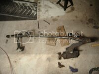
I pulled the old system out as one unit; I just unbolted the idler arm from the frame, and the tie-rods from the spindles.
Still haven't figured out why my camera always takes blurry pics, but you get the idea:
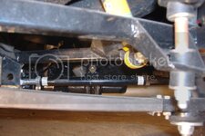
Nice and roomy now that everything is out:
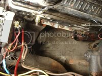
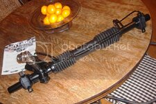
I bought a remanufactured rack for a 1992 Pontiac GrandAm from AutoZone for about $160, that's including the $80 core charge
I got the sport steer (2.5 turns lock to lock I believe), non variable assist rack AutoZone P/N 6449
The remanufactured racks DO NOT come with the brackets OR tie-rod bolts. I went to a junk yard and had them pull a rack and made sure they got the brackets to mount the rack. One thing I forgot to do was have the junk yard include the tie-rod bolts. They charged me $50 for the rack and brackets. I went to a Pontiac dealer and they told me that GM no longer manufactures this bolt, so they have to special order it from some warehouse - $28 for the two bolts :thud: (AutoZone didn't care that I brought them a standard steer rack back, although I didn't tell them I brought them a different one)
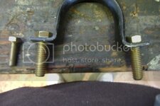
Here is the driver's side clamp for the rack. This holds 90% of the lateral forces put on the rack when steering the car. Stock, they have holes sized for the bolt on the left. That just doesn't look strong enough to me. There is plenty of meat on the bracket to drill it out for a larger bolt:
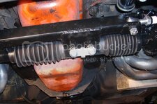
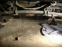
I started messing around with positioning of the rack, so I put some jack-stands under it to hold it in place while looking for a good final position. I have rope holding it up in this picture so I could move it around easier. I tried to get it tucked up as high as I could:
I chose to cut a notch in the motor mount, so I could tilt the rack input more horizontal to prevent U-joint binding: (With the box and clutch linkage out, it is surprisingly easy to get a sidemount header in place by yourself if you have the car high enough. Having the header in is essential for positioning of the rack input with the U-joints as is gets pretty close)
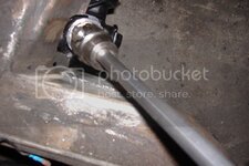
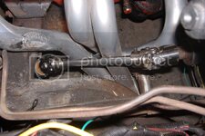
If you look closely at that last picture you will notice that I shortened my column shaft. At stock length, it is impossible to use only two regular U-joints. You should be able to hammer on the end of the shaft and it should go in as far as you need. (DO NOT hammer directly on the end of the shaft; use a block of wood or something to protect the splines at the end) If it won't budge, you can refer to my "Shortening the steering column" thread. There are a few pictures in there that should help with the disassembly of the column (already out of the car).
I used flaming river U-joints with a DD shaft on my car. The steering column is 1"-48spline and the rack is a 17mm DD.
Part numbers for the ones I used: (summit racing)
FLA-FR1712DD – 1"-48 + ¾ DD
FLA-FR1759DD – 17mm DD + ¾ DD
FLA-FR1850 –18" ¾ DD shaft –just enough to mess up once
This was the most expensive purchase of the whole project at around $180
One thing I never heard other people mention was the hard-lines that run across the rack. They hit the oil pan, and came close to the tie-rod bracket in the position I had the rack, so I straightened them out, and re-routed them to the lower rear of the rack. You can cut off the fittings on the passenger's side of the rack if you have a double flaring tool so you can make the lines shorter if need be. I used a compression fitting on one of the lines (1/4" line) to make it longer:
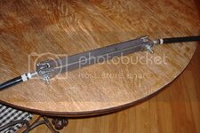
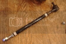
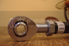
For the tie-rods, I had just done the VB&P performance upgrade last winter, so I kept my MOOG ball-joints at the spindle end, along with the HD tie-rod sleeves. For the rack end, I used a HD chrome moly heim-joint with a ½" hole and 5/8" 18 thread (1 left and 1 right-hand thread)
Part numbers (speedway motors)
91002126 – RH thread
91002326 – LH thread
These were around $45
When I had mine in the final position, I went over this little checklist to make sure everything will work in the position I had it.
-Do the U-joints bind?
-Do you have header clearance?
-Can you access the pressure and return lines for the pump?
-Do the hardlines contact anything that could chafe them over time?
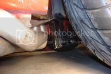
-Does the front driver's side tire clear the rack under full turn? (My 245/45/17 with a 4" backspace TT2 wheel is about 3" from the rack at full turn)
-Does the suspension come in contact with anything under full compression/droop?
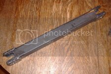
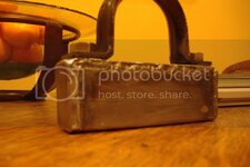
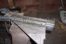
Now that everything was double checked and in alignment, I started to make some brackets. I used 1"x1.5" tubing with a 1/16th" wall thickness. The rubber mounts on the rack measure 15/16", so 1" tubing fits nicely. I braced the bracket with 1/8th" steel plate.
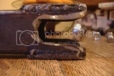
I welded nuts to the inside of the tubing, and boxed in the whole thing: (same goes for the passenger side)
All of my brackets are welded to the frame; I don't plan on returning it to stock. Although, I have seen a few nice ones (not steeroids) that were bolted to the original box mounts and the four holes on the bottom of the frame rail.
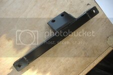
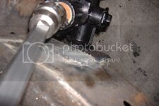
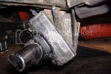
On my bracket, there is a plate that is welded to the inside of the frame rail (similar to the spot the box was mounted) and is welded to the mount in the above picture. Here it is, everything here is 1/8th" steel
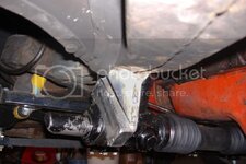
Next is the passenger side bracket. I made the same style bracket out of my 1x1.5 tubing and 1/8" bracing:
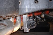
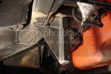
Hooker side mounts make it hard to have anything bolt up using the stock idler arm bolt holes, so mounting the bracket from the inside of the frame rail was not an option in my case. My bracket is welded to the bottom of the motor-mount, and the frame rail:
I tried to take as many pictures as I could during this project, but I probably missed a few detailed shots. You should be able to get the idea of what I am talking about with the pictures I have though.
Before taking anything apart, I drove the front wheels onto a set of Rhino Ramps. (Along with jack stands under the frame) This made it so that I could take measurements for things like tie-rod length and position with the suspension at ride height, and still be able to get under the car. (barely)
First thing I did was disassemble the old system.
It is helpful to have another person to pull out the box – I couldn't get my headers (Hooker sidemounts) out without taking the box out and the box wasn't coming out with the headers in :toilet . So I had the headers un-bolted, and moved them enough to get to the nuts securing the box to the frame. Once unbolted, I had another person hold the box from the top of the car while I was waiting to catch it from underneath the car. It's nice to have the other person there, so they can slowly let the box down to you, rather do it yourself and to have it fall on you, because the weight of the box can surprise you. I also had to pull the clutch Z-bar to get the headers out. It also just gives more room to work, even if you can take the headers out with the Z-bar still in.
I pulled the old system out as one unit; I just unbolted the idler arm from the frame, and the tie-rods from the spindles.
Still haven't figured out why my camera always takes blurry pics, but you get the idea:

Nice and roomy now that everything is out:

I bought a remanufactured rack for a 1992 Pontiac GrandAm from AutoZone for about $160, that's including the $80 core charge
I got the sport steer (2.5 turns lock to lock I believe), non variable assist rack AutoZone P/N 6449
The remanufactured racks DO NOT come with the brackets OR tie-rod bolts. I went to a junk yard and had them pull a rack and made sure they got the brackets to mount the rack. One thing I forgot to do was have the junk yard include the tie-rod bolts. They charged me $50 for the rack and brackets. I went to a Pontiac dealer and they told me that GM no longer manufactures this bolt, so they have to special order it from some warehouse - $28 for the two bolts :thud: (AutoZone didn't care that I brought them a standard steer rack back, although I didn't tell them I brought them a different one)
Here is the driver's side clamp for the rack. This holds 90% of the lateral forces put on the rack when steering the car. Stock, they have holes sized for the bolt on the left. That just doesn't look strong enough to me. There is plenty of meat on the bracket to drill it out for a larger bolt:

I started messing around with positioning of the rack, so I put some jack-stands under it to hold it in place while looking for a good final position. I have rope holding it up in this picture so I could move it around easier. I tried to get it tucked up as high as I could:

I chose to cut a notch in the motor mount, so I could tilt the rack input more horizontal to prevent U-joint binding: (With the box and clutch linkage out, it is surprisingly easy to get a sidemount header in place by yourself if you have the car high enough. Having the header in is essential for positioning of the rack input with the U-joints as is gets pretty close)


If you look closely at that last picture you will notice that I shortened my column shaft. At stock length, it is impossible to use only two regular U-joints. You should be able to hammer on the end of the shaft and it should go in as far as you need. (DO NOT hammer directly on the end of the shaft; use a block of wood or something to protect the splines at the end) If it won't budge, you can refer to my "Shortening the steering column" thread. There are a few pictures in there that should help with the disassembly of the column (already out of the car).
I used flaming river U-joints with a DD shaft on my car. The steering column is 1"-48spline and the rack is a 17mm DD.
Part numbers for the ones I used: (summit racing)
FLA-FR1712DD – 1"-48 + ¾ DD
FLA-FR1759DD – 17mm DD + ¾ DD
FLA-FR1850 –18" ¾ DD shaft –just enough to mess up once
This was the most expensive purchase of the whole project at around $180
One thing I never heard other people mention was the hard-lines that run across the rack. They hit the oil pan, and came close to the tie-rod bracket in the position I had the rack, so I straightened them out, and re-routed them to the lower rear of the rack. You can cut off the fittings on the passenger's side of the rack if you have a double flaring tool so you can make the lines shorter if need be. I used a compression fitting on one of the lines (1/4" line) to make it longer:

For the tie-rods, I had just done the VB&P performance upgrade last winter, so I kept my MOOG ball-joints at the spindle end, along with the HD tie-rod sleeves. For the rack end, I used a HD chrome moly heim-joint with a ½" hole and 5/8" 18 thread (1 left and 1 right-hand thread)
Part numbers (speedway motors)
91002126 – RH thread
91002326 – LH thread
These were around $45


When I had mine in the final position, I went over this little checklist to make sure everything will work in the position I had it.
-Do the U-joints bind?
-Do you have header clearance?
-Can you access the pressure and return lines for the pump?
-Do the hardlines contact anything that could chafe them over time?
-Does the front driver's side tire clear the rack under full turn? (My 245/45/17 with a 4" backspace TT2 wheel is about 3" from the rack at full turn)
-Does the suspension come in contact with anything under full compression/droop?
Now that everything was double checked and in alignment, I started to make some brackets. I used 1"x1.5" tubing with a 1/16th" wall thickness. The rubber mounts on the rack measure 15/16", so 1" tubing fits nicely. I braced the bracket with 1/8th" steel plate.
I welded nuts to the inside of the tubing, and boxed in the whole thing: (same goes for the passenger side)

All of my brackets are welded to the frame; I don't plan on returning it to stock. Although, I have seen a few nice ones (not steeroids) that were bolted to the original box mounts and the four holes on the bottom of the frame rail.
On my bracket, there is a plate that is welded to the inside of the frame rail (similar to the spot the box was mounted) and is welded to the mount in the above picture. Here it is, everything here is 1/8th" steel


Next is the passenger side bracket. I made the same style bracket out of my 1x1.5 tubing and 1/8" bracing:

Hooker side mounts make it hard to have anything bolt up using the stock idler arm bolt holes, so mounting the bracket from the inside of the frame rail was not an option in my case. My bracket is welded to the bottom of the motor-mount, and the frame rail:


